

Fluorescent image calibration step wedge, and use thereof in illumination for fluorescent imaging and automatic exposure
a technology of fluorescent imaging and calibration step wedge, which is applied in the direction of fluorescence/phosphorescence, luminescent dosimeter, optical radiation measurement, etc., can solve the problems of not being able to view the mouse specimen along multiple axes, the mouse's biological specimen is not possible to be seen along multiple axes, and the observation is not simplistic and the use of modern color digital cameras is not optimal
- Summary
- Abstract
- Description
- Claims
- Application Information
AI Technical Summary
Benefits of technology
Problems solved by technology
Method used
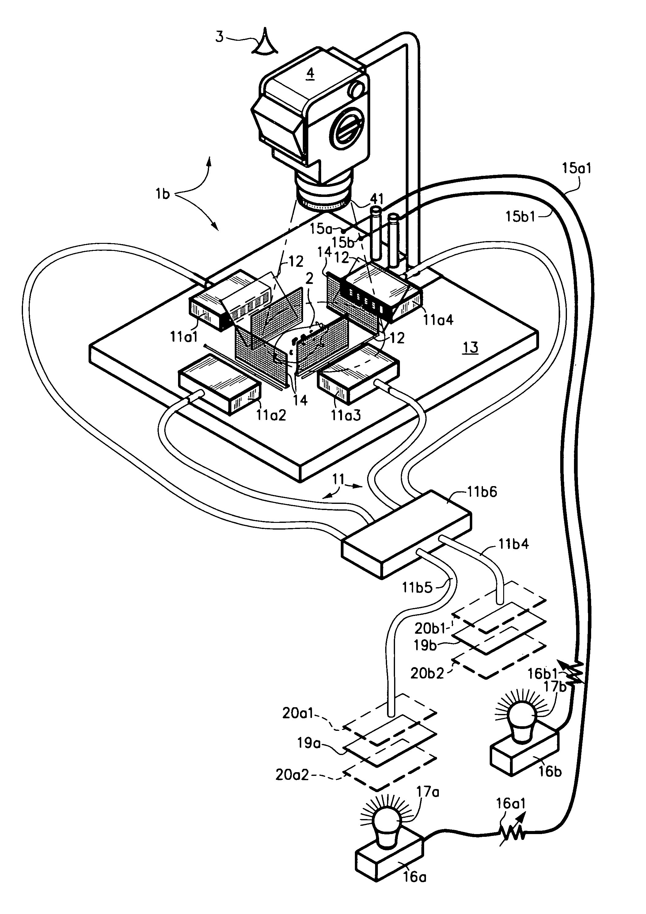
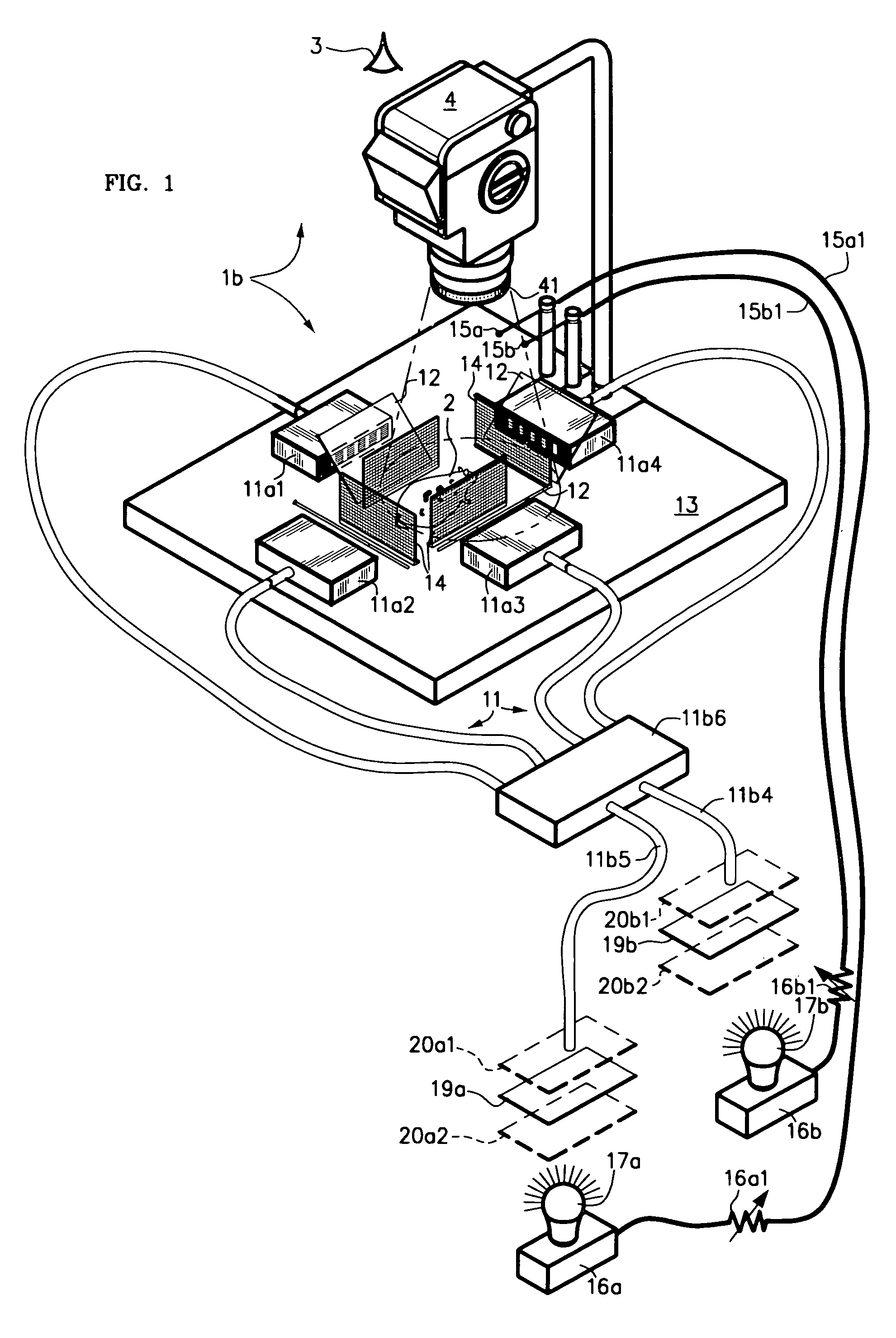
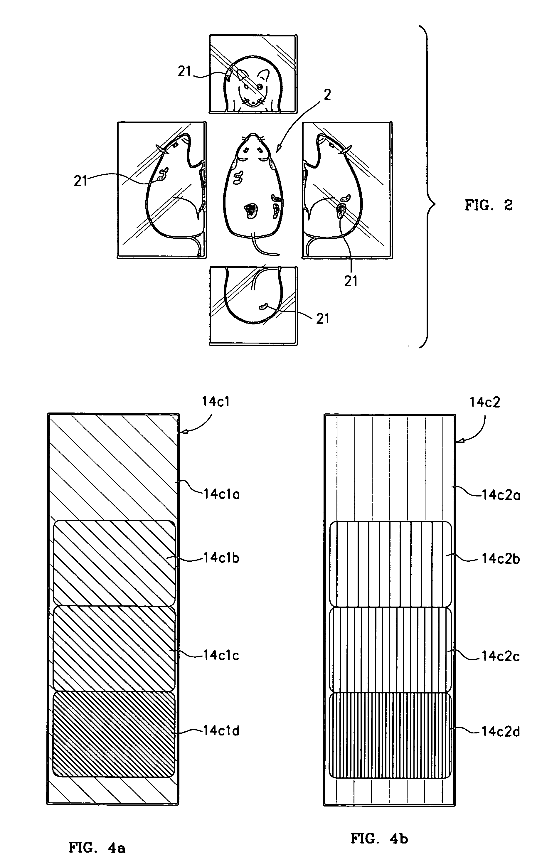
Image

Examples
Embodiment Construction
[0070]The following description is of the best mode presently contemplated for the carrying out of the invention. This description is made for the purpose of illustrating the general principles of the invention, and is not to be taken in a limiting sense. The scope of the invention is best determined by reference to the appended claims.
[0071]Although specific embodiments of the invention will now be described with reference to the drawings, it should be understood that such embodiments are by way of example only and are merely illustrative of but a small number of the many possible specific embodiments to which the principles of the invention may be applied. Various changes and modifications obvious to one skilled in the art to which the invention pertains are deemed to be within the spirit, scope and contemplation of the invention as further defined in the appended claims.
[0072]In simple terms, the present and related inventions may be considered to be directed to devices, and meth...
PUM
| Property | Measurement | Unit |
|---|---|---|
| optical density | aaaaa | aaaaa |
| optical density | aaaaa | aaaaa |
| diameter | aaaaa | aaaaa |
Abstract
Description
Claims
Application Information