Method and system for simulating processing of a workpiece with a machine tool

a technology of machine tools and workpieces, applied in the direction of electric controllers, program control, instruments, etc., can solve the problems of time-consuming, high cost, and limited significance of information obtained with these simulation programs, so as to improve the accuracy of simulation.

Active Publication Date: 2007-02-06
SIEMENS AG
View PDF16 Cites 13 Cited by
  • Summary
  • Abstract
  • Description
  • Claims
  • Application Information

AI Technical Summary

Benefits of technology

[0019]In practical applications, the behavior of the machine tool is affected not only by the application program and the real-time kernel, but also the electrical and mechanical parameters of the machine tool itself. Examples of such parameters are the dynamic response of the drives and the particulars of the mechanical characteristic of the machine tool. Advantageously, the simulation method can operate more accurately if machine parameters are provided to the computer and the computer adapts the computer-internal model of the machine tool to the provided machine parameters.
[0020]According to another feature of the invention, the controller, when providing the application program to the computer, can also transmit a selection command for selecting a control program from the control software that was provided to the computer. The computer uses the control program defined by the selection command as the simulation program, which makes the simulation method more flexible. Alternatively, the control software can be provided to the computer together with the application program, for example, via a computer-to-computer link, such as a local area network (LAN), the Internet, and a point-to-point connection (dial-up connection).
[0021]According to yet another feature of the invention, the computer may determine a result, for example in the form of a dataset, of a machining operation from the totality of determined expected actual state values and outputs the result. With this approach, a user of the simulation method can quite easily evaluate the results obtained with the simulation method.
[0023]According to yet another feature of the invention, the computer can check for a collision between the actuators of the machine tool based on the determined expected actual states and output a warning message if a likely collision is detected. In this way, dangerous states can be detected early.
[0025]Advantageously, the accuracy of the simulation can be improved further, if the computer takes into consideration previously determined expected actual states when determining new machine-dependent control commands for the machine tool and / or when determining new expected actual states of the machine tool.

Problems solved by technology

However, this approach is obviously time-consuming, requires a substantial quantity of material, and is also expensive.
The information obtained with these simulation programs has therefore only limited significance.
In addition, generating the simulation programs and adapting the simulation programs to the new functionalities of the control software represent a significant programming task.

Method used


Image

  • Method and system for simulating processing of a workpiece with a machine tool
  • Method and system for simulating processing of a workpiece with a machine tool
  • Method and system for simulating processing of a workpiece with a machine tool

Examples


Embodiment Construction

[0029]Throughout all the Figures, same or corresponding elements are generally indicated by same reference numerals. These depicted embodiments are to be understood as illustrative of the invention and not as limiting in any way. It should also be understood that the drawings are not necessarily to scale and that the embodiments are sometimes illustrated by graphic symbols, phantom lines, diagrammatic representations and fragmentary views. In certain instances, details which are not necessary for an understanding of the present invention or which render other details difficult to perceive may have been omitted.

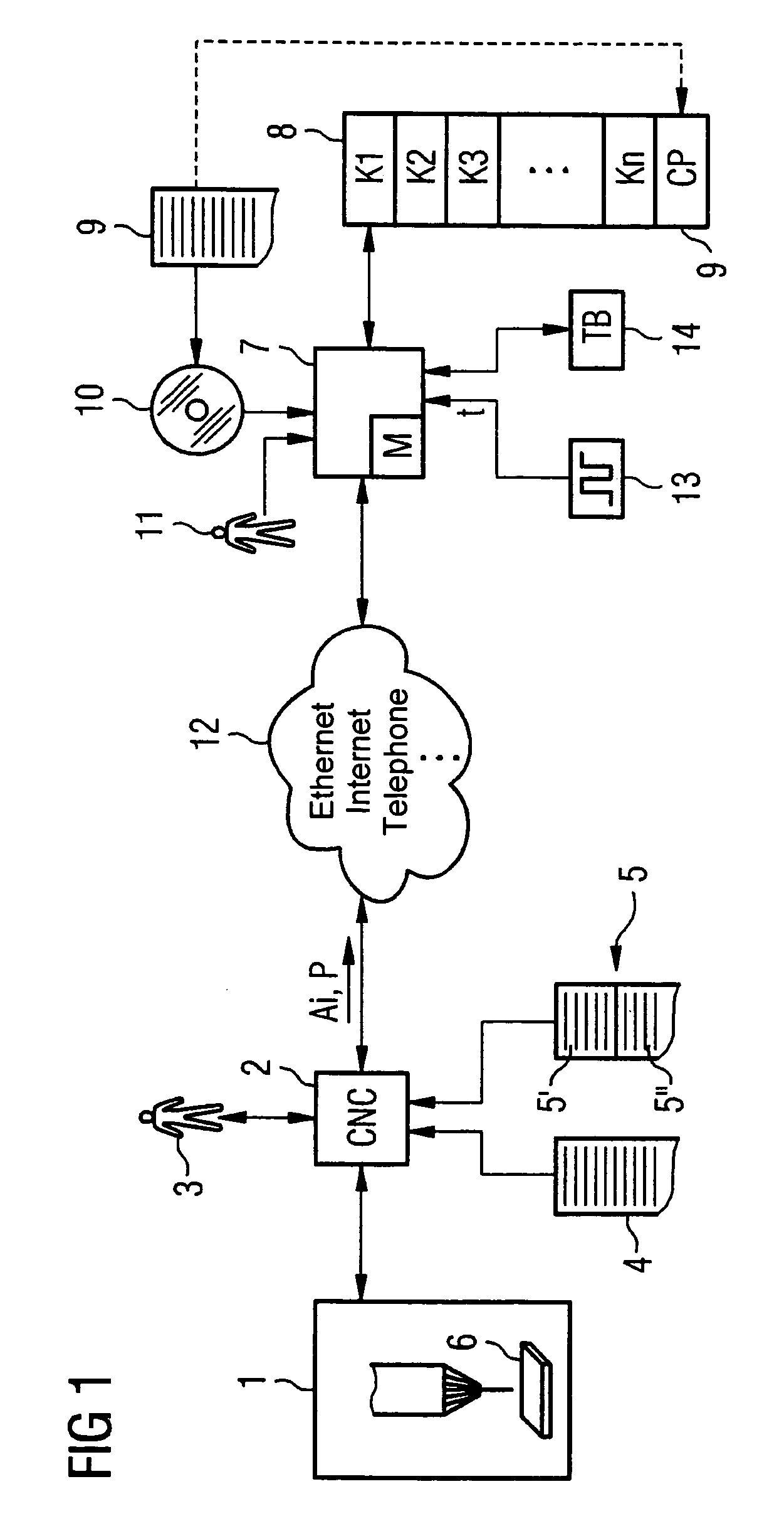
[0030]Turning now to the drawing, and in particular to FIG. 1, there is shown schematically a machine tool 1 that is controlled by a numeric controller 2 (CNC 2). The numeric controller 2 receives an application program 4, for example, from a user 3 or from a main computer (not shown). The application program 4 includes instruction steps that describe machining operations to b...


PUM


Abstract

An application program that describes processing of a workpiece by the machine tool in form of instruction steps is disclosed. A computer executes the application program and step-by-step determines based on a simulation program machine-dependent control commands for a controller. The machine-dependent control commands depend on a virtual time base that is independent of an actual time base. The computer determines based on a computer-internal model of the machine tool and the determined machine-dependent control commands expected actual states of the machine tool, thereby simulating execution of the machine-dependent control commands by the machine tool. The simulation program is implemented as control software in the controller.

Description

CROSS-REFERENCES TO RELATED APPLICATIONS[0001]This application claims the priority of German Patent Application, Ser. No. 103 52 815.6, filed Nov. 12, 2003, pursuant to 35 U.S.C. 119(a)–(d), the disclosure of which is incorporated herein by reference.BACKGROUND OF THE INVENTION[0002]The present invention relates to a method and system for simulating processing a workpiece with a machine tool. The invention is also directed to a computer program and to a computer programmed with a computer program for carrying out the method.[0003]Nothing in the following discussion of the state of the art is to be construed as an admission of prior art.[0004]Machine tools are typically controlled by numeric controllers which execute an application program that has instruction steps, for example a part program according to DIN 66025. The application program determines the process flow in the machine, e.g., the travel paths of various tools.[0005]The operating system of numeric controllers is typicall...

Claims


Application Information

Patent Timeline
Patent Type & Authority Patents(United States)
IPC IPC(8): G05B11/01G06F9/445G06G7/48G05B17/02G05B19/4069G06F19/00
CPCG05B19/4069G05B2219/49143G05B2219/35311G05B2219/35308
Inventor DOLANSKY, STEFAN
Owner SIEMENS AG
Why Eureka
Try Eureka