
Compiler and register allocation method

a register allocation and compiler technology, applied in computing, instruments, electric digital data processing, etc., can solve the problems of increasing the time required for compiling, affecting the level of the actual register, and reducing so as to achieve the effect of minimizing the number of interferences

Inactive Publication Date: 2007-02-06
IBM CORP
View PDF4 Cites 10 Cited by
  • Summary
  • Abstract
  • Description
  • Claims
  • Application Information

AI Technical Summary

Benefits of technology

The present invention relates to a method for optimizing programming efficiency in a computer by using graph coloring to allocate registers to instructions in a program. The method addresses the problem of interference between variables that may occur during parallel execution of instructions. The invention proposes a method for reducing interference between variables and avoiding the need for excessive spill code. The method involves constructing and analyzing a DAG for the program, employing an interference graph to determine which instructions may interfere with each other, and allocating registers to the instructions based on the interference graph. The invention aims to minimize interference between variables and improve programming efficiency.

Problems solved by technology

However, with this graph coloring method, which uses a parallelizable interference graph, since the latent probability of parallel execution is accepted for all instructions in a target program, the interference that could develop between variables is enormous.
And when interference between variables is increased, the following problems arise.1. The time required for compiling increases.2. The interference level exceeds the number of actual registers, and spill code is required.
Therefore, when the interference level exceeds the number of actual registers, the coloring cost is greatly increased.
Further, making a spill decision is difficult when parallel execution by the program is taken into consideration.
As is shown in FIG. 19B, for the interference graph, the number of interferences between the variables is enormous and providing an efficient register allocation process is difficult.

Method used


Image

  • Compiler and register allocation method
  • Compiler and register allocation method
  • Compiler and register allocation method

Examples


Embodiment Construction

[0051]The preferred embodiment of the present invention will now be described in detail while referring to the accompanying drawings.

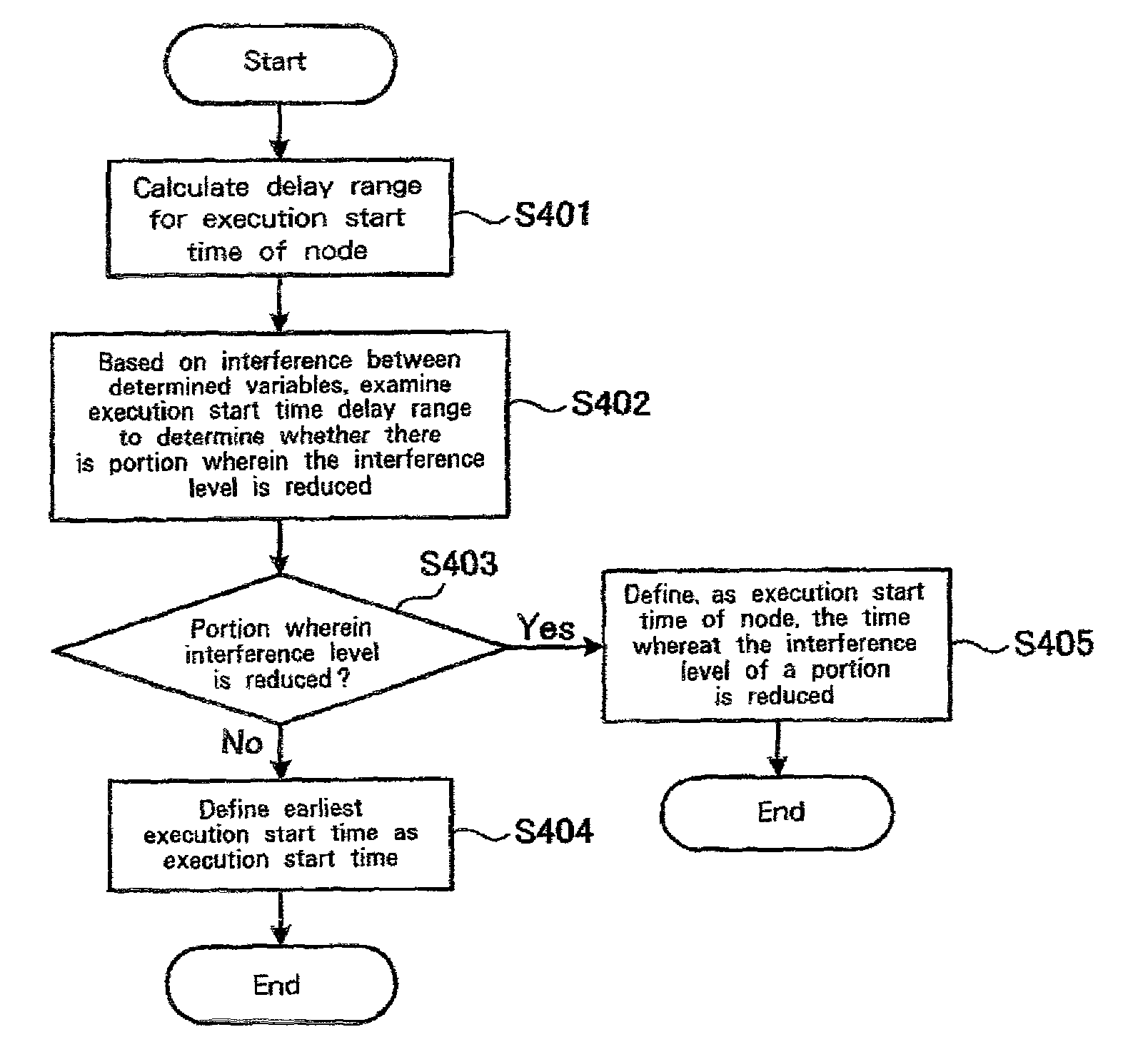
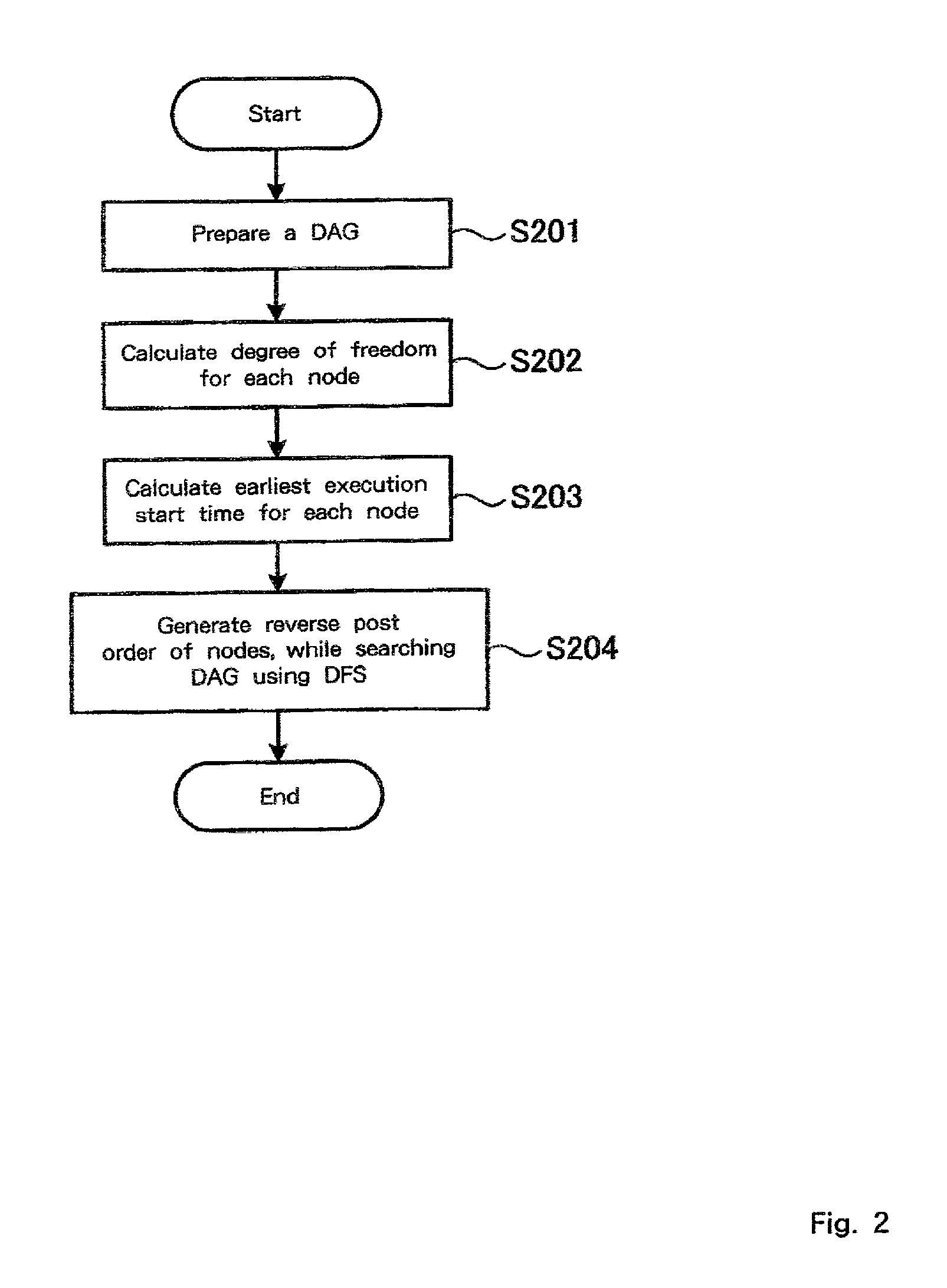
[0052]An overview of the invention will now be given. According to the invention, a DAG (Directed Acyclic Graph), a directed graph that represents the order for the execution of the instructions in a program to be compiled, is prepared, and the degree whereat each instruction affects the execution time is calculated, based on the DAG. The instructions are arranged based on an obtained degree, and an interference graph is constructed while taking into account the order in which the instructions are executed. That is, with the condition that the overall program execution time will not be extended, an interference graph is prepared that includes an interference for guaranteeing the minimum required parallel execution.

[0053]To implement this, in this invention the phase arrangement order of nodes (instructions in the program) in the DAG is determined, so t...


PUM


Abstract

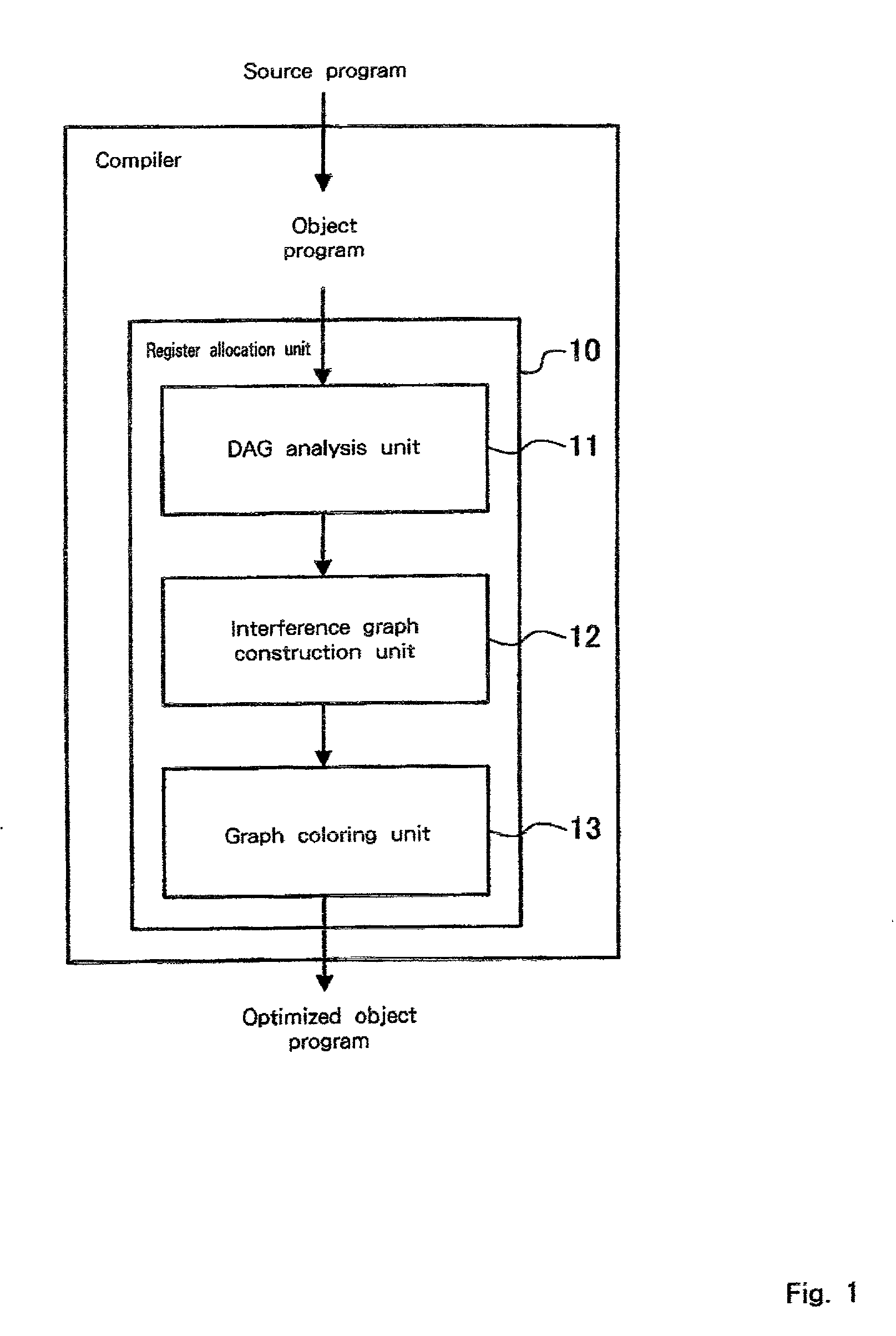
A computer, computer compiler and method for reducing the number of interferences between variables during graph coloring while maintaining the possibility that the instructions will be executed in parallel. A compiler, which converts into a machine language the source code of a program written in a programming language and optimizes the program includes: a directed acyclic graph DAG analysis unit 11 for constructing and analyzing a DAG for an instruction in a program to be processed; an interference graph construction unit 12 for employing the analysis results to construct an interference graph representing the probability that an interference will occur between variables used by the instructions; and a graph coloring unit 13 for allocating registers for the instruction based on the interference graph that is constructed.

Description

BACKGROUND OF THE INVENTION[0001]1. Field of the Invention[0002]The present invention relates to register allocation for instruction level parallel architectures.[0003]2. Related Art[0004]Generally, a program written in a programming language is optimized in many ways. As one optimization method, register allocation is conducted to obtain an effective usage of registers. According to one method for allocating registers, called coloring, a different color is assigned to each of the registers, and subsequently, registers are allocated based on the same principle as would be used for a process whereby colors were used to distinguish between program instructions.[0005]Accompanying the improvements in the hardware functions of computers, parallel processing, involving multi-programming, has become popular. Also, for the allocation of registers for compiling, a register allocation method has been proposed that reflects the parallel execution of a program. For this type of register allocat...

Claims


Application Information

Patent Timeline
Patent Type & Authority Patents(United States)
IPC IPC(8): G06F9/45
CPCG06F8/441
Inventor KOSEKI, AKIRAKOMATSU, HIDEAKI
Owner IBM CORP
Learn More