Method for controlling at least one actuator in a mass flow duct

a technology of mass flow duct and actuator, which is applied in the direction of electrical control, process and machine control, instruments, etc., can solve the problems of difficult dynamic operation, difficult to achieve optimal resolution, and complicated regulation on the basis of physical models, so as to improve the response time of an exhaust gas turbocharger for setting a desired boost pressure or a desired exhaust counterpressure, the effect of reducing the response tim

Inactive Publication Date: 2007-02-13
ROBERT BOSCH GMBH
View PDF12 Cites 42 Cited by
  • Summary
  • Abstract
  • Description
  • Claims
  • Application Information

AI Technical Summary

Benefits of technology

[0004]An example method according to the present invention for controlling at least one actuator in a mass flow duct may have the advantage that a pressure upstream from the at least one actuator in the mass flow duct is predefined, and a related variable that is characteristic for the flow resistance of the mass flow duct is determined as a function of the predefined pressure, and at least one actuator is controlled for setting this related variable characterizing the flow resistance of the mass flow duct. In this way, the predefined pressure may be set with minimum delay, so that an improved dynamic response is achieved. This is particularly advantageous for the use of the example method according to the present invention in an internal combustion engine of a vehicle, the at least one actuator being able to be implemented as a bypass valve in a bypass which is connected in parallel to a turbine of an exhaust gas turbocharger, for example. In this case, a desired exhaust gas counterpressure upstream from the turbine may be set with minimum delay, and thus a very dynamic driving response may be achieved. The corresponding control of the bypass valve may also be integrated into an existing boost pressure regulation as a pilot control.
[0005]It may be particularly advantageous if a degree of opening of the at least one actuator is selected as the variable characterizing the flow resistance. In this way, using the degree of opening, the manipulated variable of the at least one actuator may be directly influenced for setting the predefined pressure and thus the predefined pressure may be accurately set as quickly as possible.
[0006]Another advantage is that a flow rate parameter proportional to the inverse value of the flow resistance is determined from the predefined pressure, a mass flow through the mass flow duct, and a temperature of the mass flow upstream from the at least one actuator in the mass flow duct; and the value characterizing the flow resistance is derived from the flow rate parameter. In this way, the value characterizing the flow resistance is determined in a particularly simple and cost-effective manner from the predefined pressure.

Problems solved by technology

The delay due to the controlled system and the fact that the way the control device affects the controlled variable is reversed in certain operating ranges both result in the regulation on the basis of a physical model being very complicated.
While it is possible to set the steady-state operating points using setpoint values for the position of the bypass valve or to set the boost pressure using a characteristics map, difficulties arise in dynamic operation for which such a regulation structure does not provide optimum resolution.

Method used


Image

  • Method for controlling at least one actuator in a mass flow duct
  • Method for controlling at least one actuator in a mass flow duct
  • Method for controlling at least one actuator in a mass flow duct

Examples


Embodiment Construction

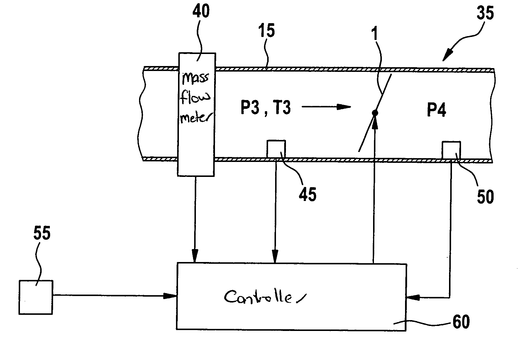
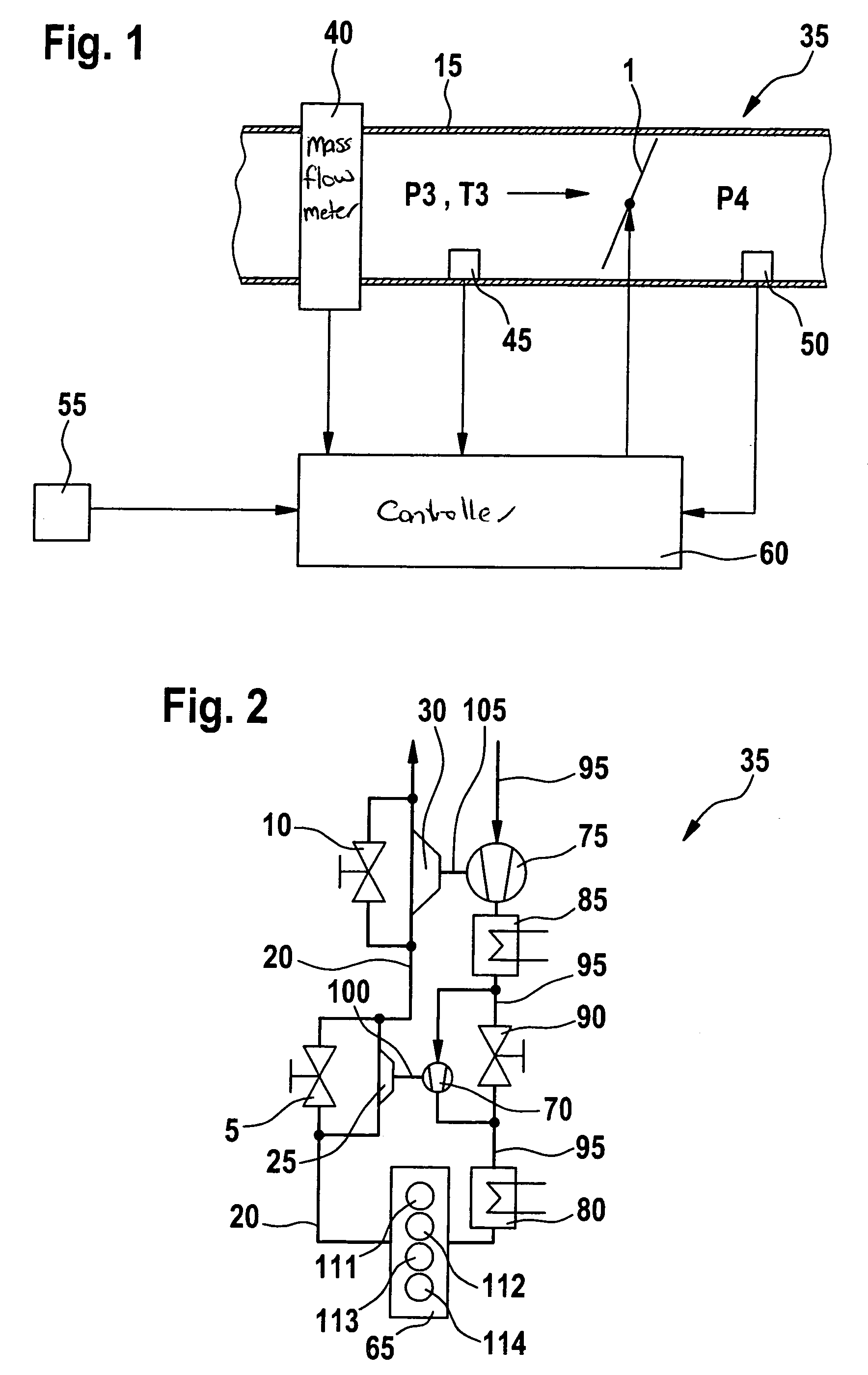
[0019]In FIG. 1, reference numeral 15 designates a mass flow duct. Mass flow duct 15 may be a component of an internal combustion engine 35, for example. Internal combustion engine 35 may drive a vehicle, for example. An actuator 1 is situated in mass flow duct 15. Actuator 1 may be designed as a throttle valve, for example. In this case, mass flow duct 15 represents an air supply of internal combustion engine 35, via which fresh air may be supplied to one or more cylinders 111, 112, 113, 114 of internal combustion engine 35. Actuator 1 may also be an exhaust recirculation valve. In this case, mass flow duct 15 represents an exhaust recirculation channel of internal combustion engine 35, via which exhaust gas may be recirculated from an exhaust system branch 20 of internal combustion engine 35 into the air supply of internal combustion engine 35. Actuator 1 may also be implemented as a bypass valve in a bypass of internal combustion engine 35. Such a bypass may bypass the throttle v...


PUM


Abstract

A method for controlling at least one actuator in a mass flow duct, which makes it possible to implement a predefined pressure upstream from the at least one actuator more rapidly. The flow resistance of the mass flow duct is modified by controlling the at least one actuator. A pressure upstream from the at least one actuator in the mass flow duct is predefined. A variable characterizing the flow resistance of the mass flow duct is determined as a function of the predefined pressure. The at least one actuator is controlled to set the related variable characterizing the flow resistance of the mass flow duct.

Description

FIELD OF THE INVENTION[0001]The present invention is directed to a method for controlling at least one actuator in a mass flow duct.BACKGROUND INFORMATION[0002]Methods for controlling at least one actuator in a mass flow duct are already known, in which the flow resistance of the mass flow duct is modified by controlling the at least one actuator. Such an actuator is a bypass valve in a bypass, for example, which is connected in parallel to a turbine of an exhaust gas turbocharger in an exhaust system branch of an internal combustion engine. A desired boost pressure in an intake pipe of the engine downstream from a compressor of the exhaust gas turbocharger may be set by suitably controlling the bypass valve.[0003]The turbocharged engine is currently usually regulated with regard to the boost pressure. In this case, the pressure in the intake pipe downstream from the compressor is the controlled variable and the position of the bypass valve is the manipulated variable. The delay due...

Claims


Application Information

Patent Timeline
Patent Type & Authority Patents(United States)
IPC IPC(8): G01M19/00F02B37/18F02B37/00F02B37/22F02D9/02F02D11/06F02D21/08F02D23/00G01M99/00G05D7/06G05D16/20
CPCF02B37/013F02B37/18F02B37/22F02D41/0007F02B37/004G05D7/0635F02D41/0065F02D41/0077Y02T10/144Y02T10/47Y02T10/12Y02T10/40
Inventor FISCHER, REINHARDBECKER, BODOWEINER, MARTINVOGT, GUENTHERWITTMER, ANDRE
Owner ROBERT BOSCH GMBH
Why Eureka
Try Eureka