
Hydraulic tensioner

a technology of hydraulic tensioner and tensioner body, which is applied in the direction of mechanical equipment, belts/chains/gearrings, and mechanical equipment, etc., can solve the problems of high manufacturing cost and difficult assembly of tensioners, and achieve the effect of reducing risk, facilitating press fitting, and suppressing backlash and flutter

Inactive Publication Date: 2007-02-13
TSUBAKIMOTO CHAIN CO
View PDF13 Cites 62 Cited by
  • Summary
  • Abstract
  • Description
  • Claims
  • Application Information

AI Technical Summary

Benefits of technology

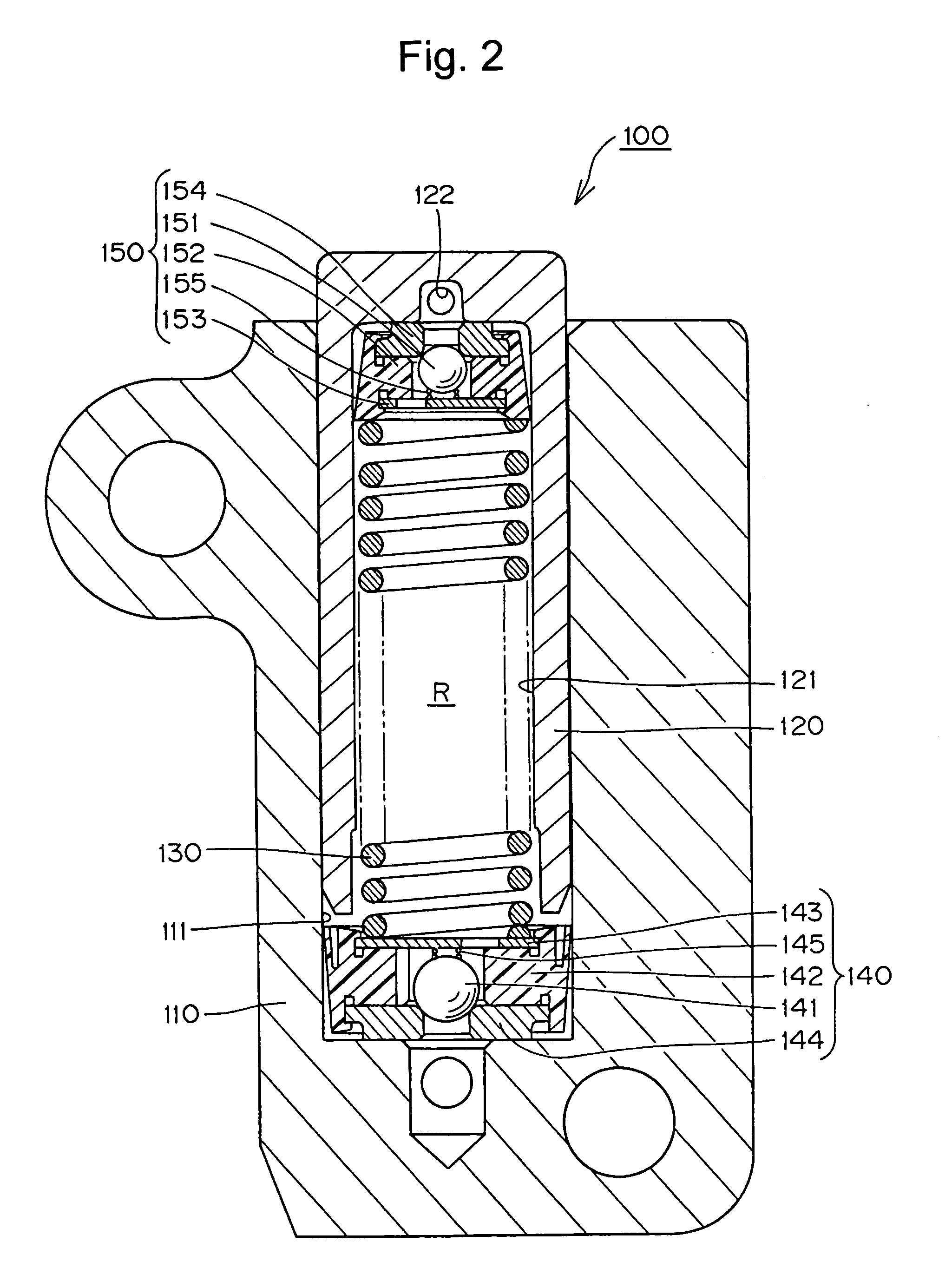
[0012]The deairing valve unit within the plunger suppresses backlash and fluttering due to excessive changes in tension in the timing belt, timing chain or the like, and particularly backlash and fluttering due to the influence of air in the high pressure oil chamber at engine start-up. Since the check ball in the deairing valve unit is biased by a ball valve biasing spring toward the end wall of the interior of the plunger, the difficulties in setting the clearance in the spiral groove deairing structure of a conventional hydraulic tensioner are avoided. Moreover, even when the plunger is pushed back by an excessive force, outflow of a pressure oil is blocked, and the pressure within the high pressure oil chamber can be maintained. However, when a negative pressure has existed inside of the housing, air which has entered the housing be easily exhausted through a vent provided in the protruding end of the plunger.
[0013]When a check valve unit is incorporated into the bottom of the plunger-receiving hole to block the backflow of oil from the high pressure oil chamber, even if the plunger is rapidly moved backward by an excessive increase in tension, the tensioner can resist the impact force by preventing oil from flowing out of the high pressure chamber toward the oil supply.
[0014]When the retainer and the ball seat of the deairing valve unit are secured by flanges formed by portions of the wall of the synthetic resin ball guide so that the flanges serve as caulking, the retainer and the ball seat are firmly integrated with the ball guide so that they will not be dropped in the assembly process, and the steps carried out in the assembly of the tensioner, including the incorporation of the deairing valve unit into the interior of the plunger are significantly simplified.
[0015]The tapered configuration of the ball guide of the deairing unit facilitates the press-fitting of the deairing valve unit into the interior of the plunger, so that the deairing valve unit can be reliably and firmly incorporated into the plunger without a reduced risk of dropping the deairing valve unit in the assembly process.
[0016]Furthermore, when the plunger biasing means comprises of an outer spring, which abuts the ball guide, and an inner spring, disposed coaxially inside the outer spring, the check valve unit can be more firmly fixed to the bottom of the plunger-receiving hole, and the tensioner can resist a strong impact force so that a backlash and fluttering of a timing belt, a timing chain or the like can be significantly suppressed.

Problems solved by technology

Another problem with the tensioner of FIGS. 9 and 10 is that the pressure relief valve assembly 540 and the air vent disc 550 are separately manufactured parts, and must be handled separately in the process of assembly of the tensioner.
Consequently, assembly of the tensioner is difficult, and its cost of manufacture is high.

Method used


Image

  • Hydraulic tensioner
  • Hydraulic tensioner
  • Hydraulic tensioner

Examples


second embodiment

[0046]The tensioner 200 in accordance with a second embodiment the invention is shown in FIG. 7. This tensioner differs from the tensioner previously described principally in that it includes a plunger-biasing structure 230 comprising an outer spring 231, and an inner spring 232. The outer spring abuts a retainer 243 in a check valve unit 240, and a ball guide 252 in a deairing valve unit 250. The inner spring 232 is coaxial with, and disposed inside, the outer spring. The inner spring abuts retainer 243 of the check valve unit 240 and a retainer 253 of the deairing valve unit. Otherwise, the configuration of the hydraulic tensioner 200 is substantially the same as that of hydraulic tensioner 100. Elements of tensioner 200 shown in FIG. 7 corresponding to those of tensioner 100 are denoted by corresponding reference numbers in the two hundred series.

[0047]Since the hydraulic tensioner 200 includes an outer spring 231 and an inner spring 232 arranged coaxially, even if the plunger is...

third embodiment

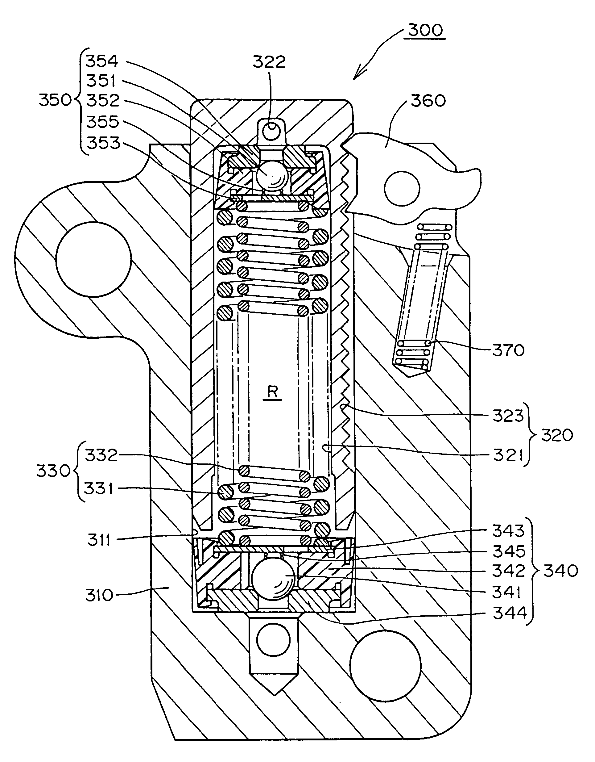
[0049]The tensioner 300 in accordance with a third embodiment the invention is shown in FIG. 8. This tensioner is similar to the dual spring tensioner 200 of FIG. 7, but differs from tensioner 200 in that the plunger is provided with a ratchet mechanism which blocks the backward movement of the plunger 320 by engagement between a rack 323 formed on the plunger 320 and a pawl 360 pivoted on the housing 310. Otherwise the tensioner 300 is substantially similar to the tensioner 200 of FIG. 7, and elements of tensioner 300, shown in FIG. 8, corresponding to those of tensioner 200, shown in FIG. 7, are denoted by corresponding reference numbers in the three hundred series.

[0050]As in the case of tensioner 200, if the plunger 320 is moved backward rapidly by an excessively large increase in tension, the springs 331 and 332 exhibit a sufficient elastic force to resist the impact, so that a backlash and fluttering are significantly suppressed. The ratchet mechanism limits backward movement ...


PUM


Abstract

In a hydraulic tensioner, a deairing valve unit comprising a synthetic resin ball guide, a check ball a biasing spring, a ball seat, and a retaining disc, is press-fit into a hollow plunger, and disposed adjacent the protruding end of the plunger. The ball and seat of the deairing valve unit are arranged to block flow of oil out of the tensioner when the oil is under pressure, but open to allow air to flow out of the tensioner, through a vent in the protruding end of the plunger, after a negative pressure condition occurs inside the oil chamber of the tensioner.

Description

FIELD OF THE INVENTION[0001]This invention relates to hydraulic tensioners for applying proper tension to endless, flexible, traveling power transmission media, for example, timing belts or timing chains which transmit rotation between the crankshaft and one or more camshafts of an internal combustion engine. The invention relates more particularly to an improved deairing mechanism for venting air from the high pressure oil chamber of a hydraulic tensioner.BACKGROUND OF THE INVENTION[0002]Hydraulic tensioners are widely used to suppress backlash and vibration due to a changes in tension in timing belts and timing chains. A typical hydraulic tensioner comprises a plunger slidable in, and protruding from, a housing. The plunger and housing cooperate to provide a high pressure oil chamber into which oil is introduced through a ball-type check valve. FIGS. 9 and 10 show a conventional hydraulic tensioner 500 having an air venting feature. In the tensioner, a hollow plunger 520 is slidab...

Claims


Application Information

Patent Timeline
Patent Type & Authority Patents(United States)
IPC IPC(8): F16H21/44F16H21/54F16H25/18F16H7/08
CPCF16H7/0836F16H2007/0806F16H2007/0859F16H2007/0817F16H2007/0853F16H2007/0812F16H2007/0891
Inventor YOSHIDA, OSAMUMIYAKE, HIROYUKI
Owner TSUBAKIMOTO CHAIN CO
Learn More