Card reader

a card reader and card medium technology, applied in the field of card readers, can solve the problems of ic card penetration, ic chip damage, card medium peeling, etc., and achieve the effect of reducing the locking for

Active Publication Date: 2007-02-13
SANKYO SEIKI MFG CO LTD
View PDF5 Cites 21 Cited by
  • Summary
  • Abstract
  • Description
  • Claims
  • Application Information

AI Technical Summary

Benefits of technology

[0021]Namely, the damaging force can be reduced by increasing the rotational speed or it can be increased by decreasing the rotational speed. Furthermore, it is possible to exert control so that the needle protrudes with a weak force, strikes the card medium, and then intensifies its pressure.
[0037]In this case, if the card medium is pushed back in reverse by a wrongful action, the lock member rotates in reverse to decrease the locking force on the card medium. To prevent such inexpedience, the push-back prevention locking mechanism can be operated to block the backward motion of the movable member and effect locking.

Problems solved by technology

Therefore, when the card medium stops abnormally in the card reader, the driving device causes the needle to protrude from the rear side of the IC chip, if the card medium is pulled out, the needle penetrates the IC card to damage the IC chip or peels it from the card medium.
As a result, the card medium cannot be used even if it is pulled out forcibly.

Method used


Image

  • Card reader
  • Card reader
  • Card reader

Examples


Embodiment Construction

[0050]The constitution of the present invention is described in detail below, with reference to the embodiments shown in the figures.

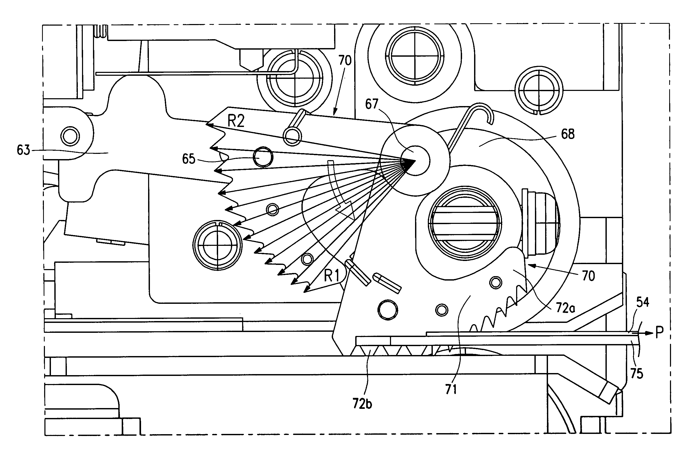
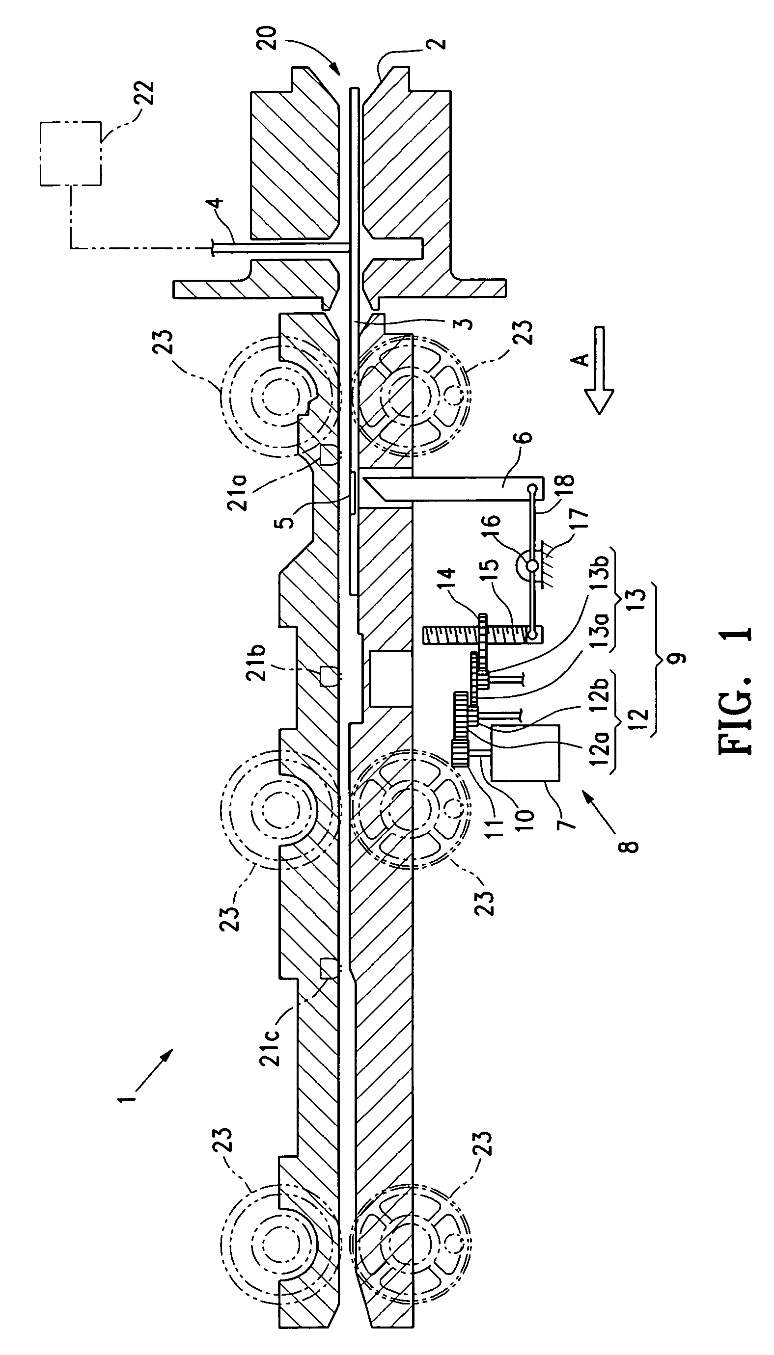
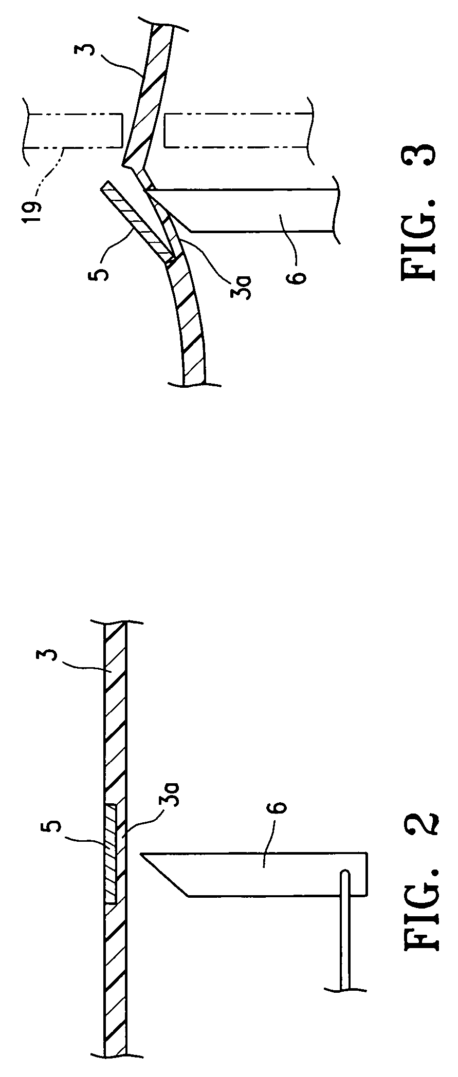
[0051]One example of an embodiment of a card reader 1 of the present invention is shown in FIG. 1–3. Card reader 1 conveys IC card 3, which is a card medium provided with IC chip 5, in card path 20 by means of drive roller 23 rotationally driven by a drive motor to perform a predetermined processing. Card reader 1 is provided with needle 6 that can protrude from the rear side of IC chip 5 by piercing card path 20 at the location where IC chip 5 on IC card 3 is being conveyed, and provided with peeling mechanism 8 that has driving device 7 to effect protrusion of needle 6.

[0052]When IC card 3 is abnormally stopped in card reader 1, driving device 7 causes needle 6 to protrude and peel IC chip 5 from IC card 3.

[0053]Driving device 7 is a motor. Therefore, a damaging force to IC card 3 can be adjusted by adjusting the rotational speed of driving device 7....


PUM


Abstract

A card reader includes a card locking mechanism locking a card medium in an immovable holding position when the card medium inserted from a card insertion port provided in a front section of a card reader body stops because of abnormal stopping, thus preventing wrongful removal of the card medium by withdrawal. The card locking mechanism includes a spindle able to rotate via a spindle pin at one end inside the card reader body at the card insertion port, and a stopper configuration enabling direct contact with a surface of the card medium provided along a periphery at another end. A rotation radius includes a distance from the spindle pin to the stopper configuration being gradually increased from one end of the stopper configuration to another end to increase locking force by contact with the card medium.

Description

BACKGROUND OF THE INVENTION[0001]1. Field of the Invention[0002]The present invention relates to a card reader. More specifically, the present invention relates to a configuration for preventing fraudulent use of a card medium in a card reader.[0003]2. Description of Related Art[0004]In card reader 101 of conventional technology, as shown in FIG. 10, the security of card reader 101 is achieved by providing shutter 102 that is opened or closed by a solenoid, for example, in a card insertion port to prevent the insertion of a foreign object other than card medium 103, and also to prevent theft by fraudulent removal of card medium 103 which is caught in card reader 101.[0005]Card reader 101 is provided with shutter 102 such that if card medium 103 is inserted from insertion port 104, shutter 102 retreats from the card path and the inserted card medium 103 is taken into card reader 101.[0006]Moreover, if card medium 103 enters beyond shutter 102, the shutter 102 closes to prevent withdr...

Claims


Application Information

Patent Timeline
Patent Type & Authority Patents(United States)
IPC IPC(8): G06K7/08G06K7/00G06K13/00G06K13/08
CPCG06K7/0013G06K7/0091G06K13/0875G06K13/085G06K13/08
Inventor OGUCHI, KOJI
Owner SANKYO SEIKI MFG CO LTD
Why Eureka
Try Eureka