Spring-lock type clamp device

a technology of spring lock and clamp device, which is applied in the direction of positioning apparatus, metal-working machine components, manufacturing tools, etc., can solve the problems of small locking force and more visible problem, and achieve the effect of compact size and reduced height of locking-use springs

Inactive Publication Date: 2007-02-13
KOSMEK LTD (JP)
View PDF6 Cites 16 Cited by
  • Summary
  • Abstract
  • Description
  • Claims
  • Application Information

AI Technical Summary

Benefits of technology

[0013]To switch the clamping apparatus from a released state to a locked state, it is only required to discharge the pressurized fluid in the release chamber and to move the annular piston toward the leading end by an urging force of the spring. Then, the pressing surface of the annular piston moves the output member toward the leading end via the first inclined surface, the rolling members and the second inclined surface, which makes the moving stroke of the output member larger than that of the annular piston. Therefore, an expanding amount of the spring is smaller compared with the moving stroke of the output member. It follows that the spring with a little expanding amount strongly drives the input surface of the output member toward the leading end for locking via the pressing surface and the rolling members.
[0014]As described above, when the output member is moved toward the leading end for locking, the expanding amount of the spring is smaller compared with the moving stroke of the output member, which enables a work or the like to be locked with a large urging force of the spring. Thereby, a spring-type clamping apparatus with a strong locking force can be provided.
[0016]In the present invention, it is preferable that the first inclined surface 41 is formed by a tapered inner peripheral surface, the second inclined surface 52 is formed by a tapered outer peripheral surface and the rolling members 55 are composed of balls or rollers. In this case, the stroke enlargement mechanism can be mechanically simple and inexpensive to manufacture.
[0019]In this invention, the pressure of the pressurized fluid supplied to the release chamber can drive the output member toward the base end for releasing by making this pressure act on an annular sectional area, which corresponds to a difference between two sectional areas of the sealing portions, by which the driving means can be mechanically simple.
[0022]According to this invention, it is possible to significantly reduce the height of the locking-use spring by applying the present invention to a link-type clamp having an idling stroke that is comparatively larger compared with other types of clamping apparatuses, whereby the link-type clamp can be compact in size.

Problems solved by technology

As a result, the urging force for the locking operation decreases, resulting in a small locking force.
The larger the idling stroke of the clamping apparatus is, the more conspicuous this problem grows.

Method used


Image

  • Spring-lock type clamp device
  • Spring-lock type clamp device
  • Spring-lock type clamp device

Examples


Embodiment Construction

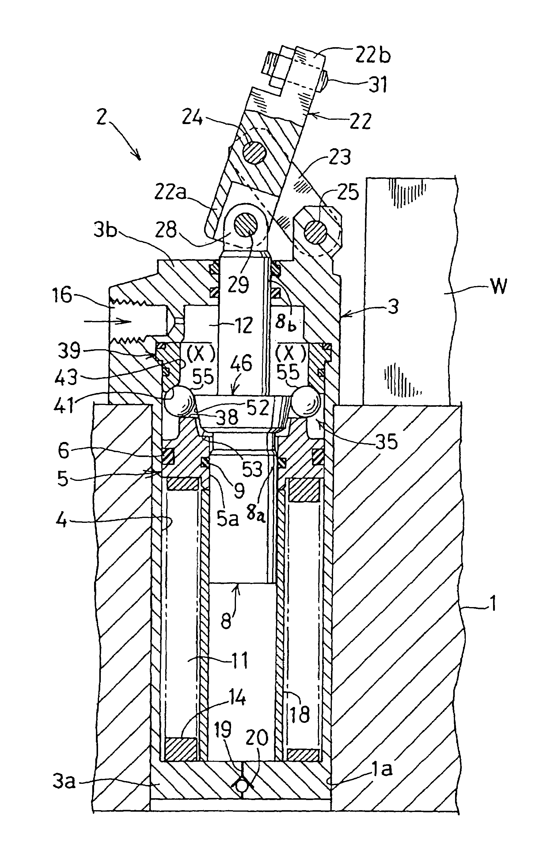
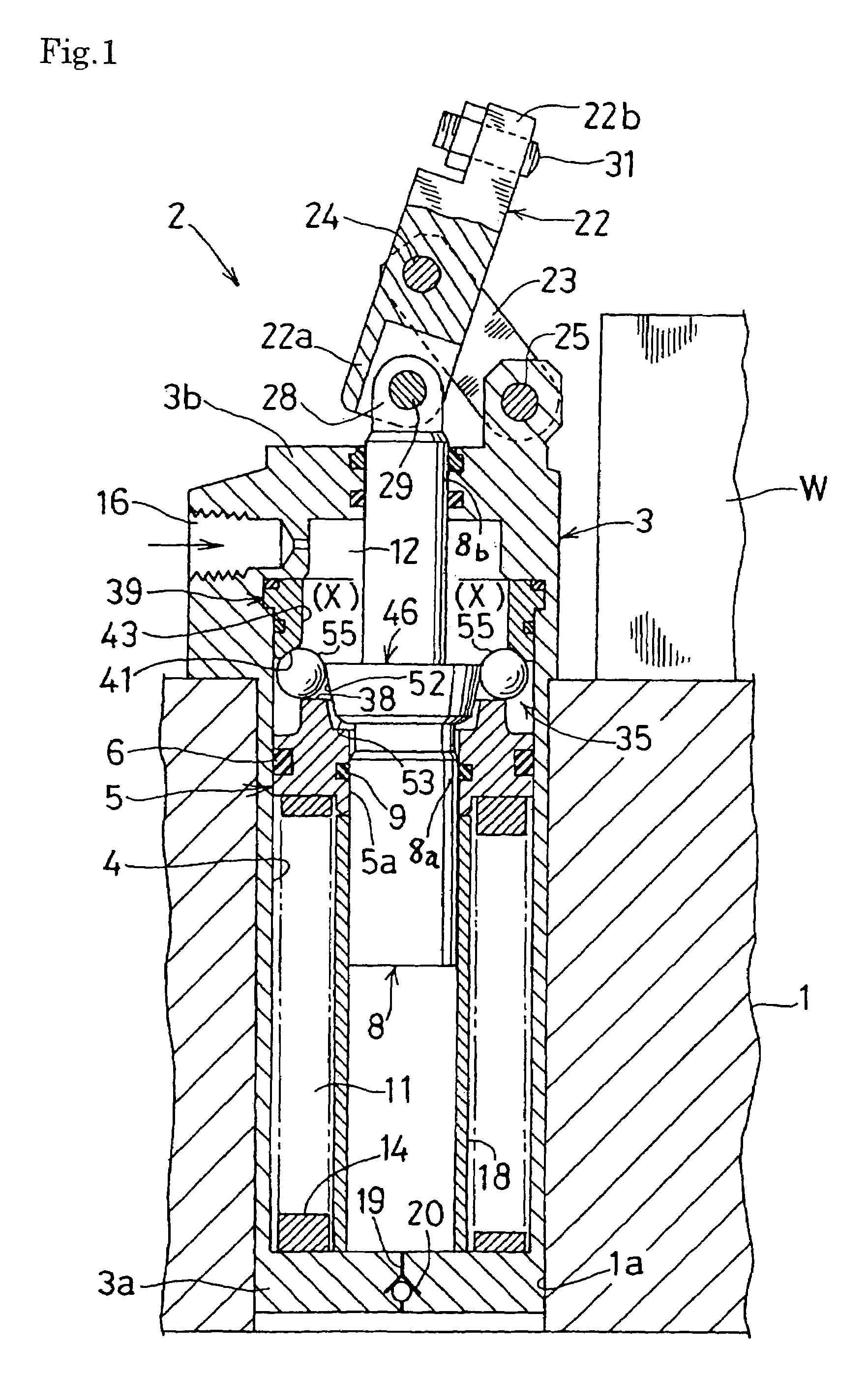
[0027]FIG. 1 through FIG. 3 show an embodiment according to the present invention. In this embodiment, it is illustrated that the present invention is applied to a link-type clamp.

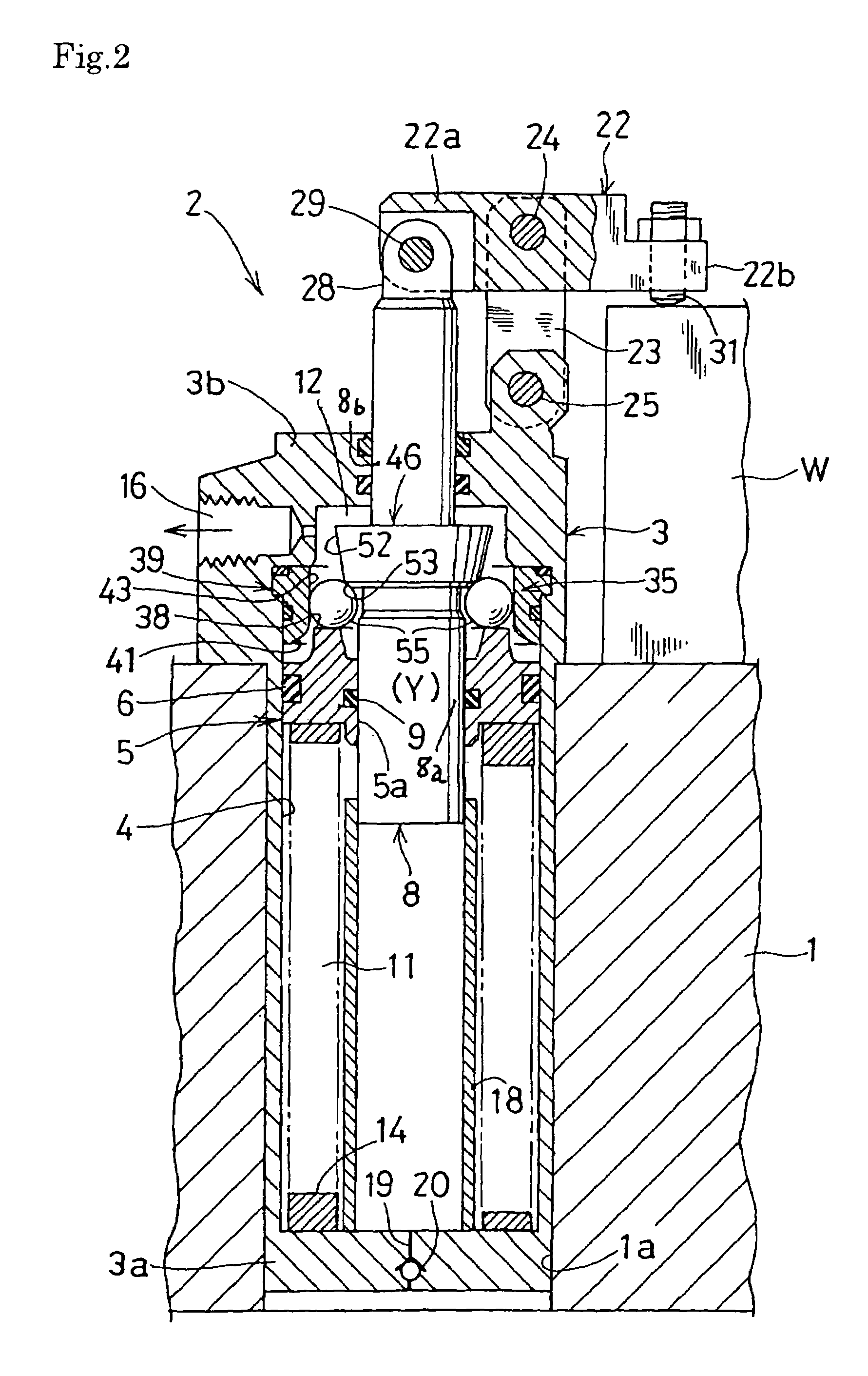
[0028]An entire structure of the link-type clamp is first described as follows with reference to FIG. 1 and FIG. 2.

[0029]A housing 3 of the clamp 2 is inserted into an installation hole 1a of a table 1 of a machine tool, and the housing 3 is fixed to an upper surface of the table 1 by a plurality of bolts (not shown in the figures).

[0030]Into a cylindrical hole 4 of the housing 3 is inserted an annular piston 5 via a first sealing member 6 hermetically and axially movably. Into a cylindrical hole 5a of the annular piston 5 is inserted a lower sealing portion 8a of an output rod 8 via a second sealing member 9 hermetically and axially movably.

[0031]Between a lower end wall (a base end wall) 3a of the housing 3 and the annular piston 5 is formed a lock chamber 11, and between an upper end wall (a leading end...


PUM


Abstract

Into a housing (3) is hermetically inserted an annular piston (5), and into the annular piston (5) is hermetically inserted an output rod (8). A spring (14) located below the piston (5) moves the piston (5) upward for locking, pressurized oil in a release chamber (12) formed above the piston (5) moves the piston (5) downward for releasing. On an upper surface of the piston (5) is provided a pressing surface (38), on an inner periphery of a peripheral wall of the release chamber (12) is provided a first tapered surface (41), which narrows upward, and on an outer periphery of the output rod (8) is provided a second tapered surface (52), which narrows downward. Between the pressing surface (38), the first tapered surface (41) and the second tapered surface (52) are inserted a plurality of balls (55) circumferentially at intervals. Thereby, when the spring (14) moves the piston (5) upward for locking, a moving stroke of the output rod (8) is larger than that of the piston (5).

Description

TECHNICAL FIELD[0001]The present invention relates to a clamping apparatus that locks by an urging force of a spring.BACKGROUND OF THE INVENTION[0002]This kind of clamping apparatuses is described in Japanese Patent Public Disclosure No. 10-277858, for example.[0003]This prior art is composed so that, during a locking operation, a compression spring composed of a plurality of coned disc springs moves a plurality of balls from a disengaging position to an engaging position, and then the compression spring axially drives an insertion pin via the balls, which are in the engaging position, for locking.[0004]By the way, an urging force of the compression spring is maximized in a fully compressed state, and decreases as the spring expands.[0005]Therefore, in the prior art, the urging force of the compression spring decreases according to an idling stroke for moving the balls from the disengaging positions to the engaging positions. As a result, the urging force for the locking operation d...

Claims


Application Information

Patent Timeline
Patent Type & Authority Patents(United States)
IPC IPC(8): B23Q3/08B23Q3/06B25B5/06B25B5/16F15B15/02F15B15/20
CPCB25B5/06B25B5/061F15B15/204B25B5/16B25B5/064B23Q3/06
Inventor YONEZAWA, KEITARO
Owner KOSMEK LTD (JP)
Why Eureka
Try Eureka