Suction device and suction method for the disposal of dust in milling machines
a technology of suction device and milling machine, which is applied in the direction of cutting machines, roads, construction, etc., can solve the problems of affecting the operation, affecting the operation, and affecting the operation so as to achieve the effect of reducing the requirements of the milling machine and improving the efficiency
- Summary
- Abstract
- Description
- Claims
- Application Information
AI Technical Summary
Benefits of technology
Problems solved by technology
Method used
Image
Examples
second embodiment
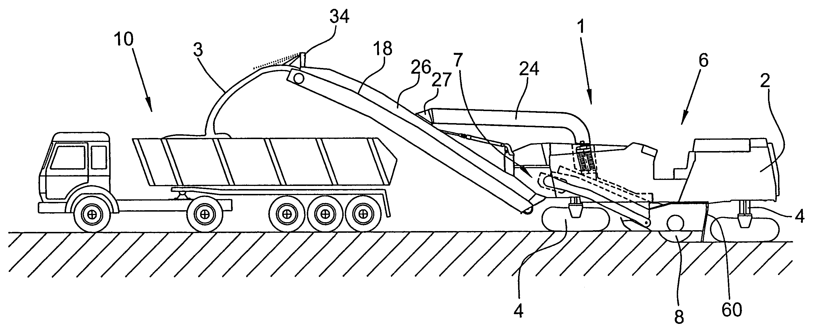
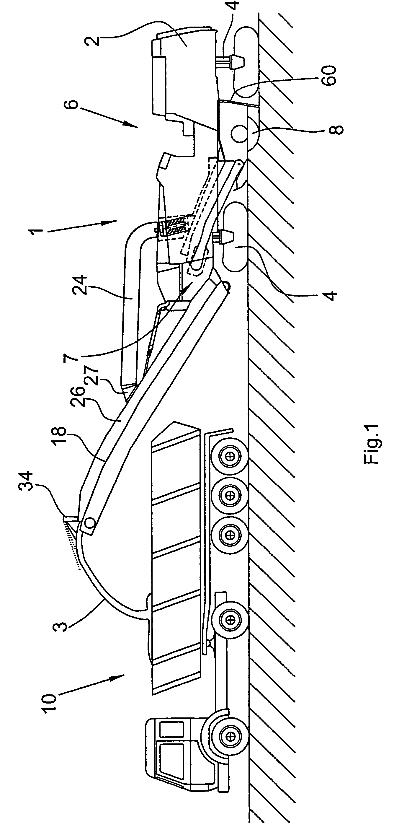
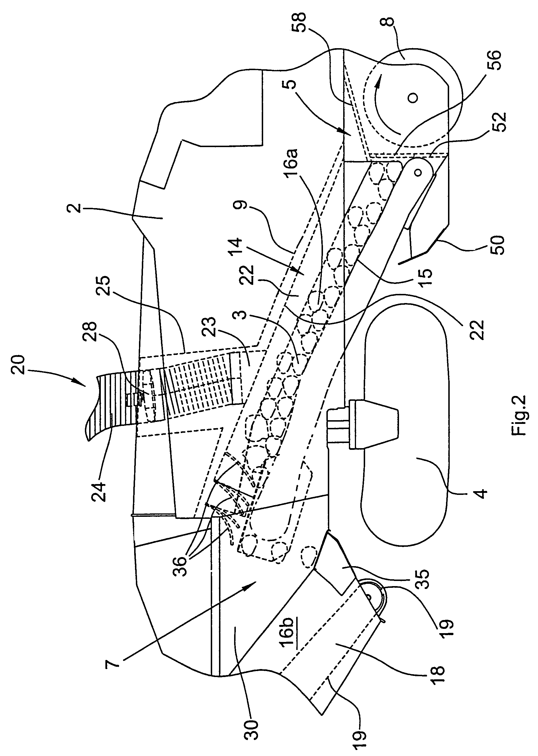
[0058]FIG. 5 shows the invention with reference to the example of a rear loader milling machine 11 with only a single conveying device 14. In a rear loader milling machine, the passage opening for the milled-off material 3 is located in the wall 61 of the drum box 58, which points towards the direction opposite to the traveling direction and is configured as a stripper. Directly at this transfer location 5, the material 3 milled off by the milling drum 8 is transferred onto the band conveyor of the single conveying device 14, which is arranged at the rear end of the rear loader milling machine 11. The conveyor belt 15 of the conveying device 14 conveys the milled-off material onto a transport vehicle 10. Like the conveying device 18 of the embodiment of FIG. 1, the conveying device 14 is pivotable in its inclination as well as laterally.
first embodiment
[0059]As can be seen from FIG. 5, the connection piece 23 is directly connected to an upper hood portion 22a of the conveying device 14 at the lower end. As in the first embodiment, flexible flaps 36 abutting on the carrying run 15a of the conveyor belt 15, as is fundamentally apparent from FIG. 4, serve as separating means between the duct sections 16a,16b. Preferably, several flaps are arranged behind each other, which permit an unhindered transport of the milled-off material 3 from the first duct section 16a into the second duct section 16b but largely prevent an airflow between the two duct sections 16a, 16b. The polluted air sucked off via the suction duct 24 reenters into the duct 16 at the upper end of the conveying device 14, namely into the duct section 16b near the discharge end of the conveying device 14.
[0060]FIG. 6 shows a second embodiment of a hood 22 formed of two hood portions 22a,22b.
[0061]Compared with the embodiment of FIG. 3, the sealing lips 46 may be omitted;...
PUM
 Abstract
Description
Claims
Application Information
 - R&D
- Intellectual Property
- Life Sciences
- Materials
- Tech Scout
- Unparalleled Data Quality
- Higher Quality Content
- 60% Fewer Hallucinations
Browse by: Latest US Patents, China's latest patents, Technical Efficacy Thesaurus, Application Domain, Technology Topic, Popular Technical Reports.
© 2025 PatSnap. All rights reserved.Legal|Privacy policy|Modern Slavery Act Transparency Statement|Sitemap|About US| Contact US: help@patsnap.com


