Method and apparatus for controlling the polarization of an optical signal

a technology of optical signal and polarization state, applied in the direction of electrical apparatus, instrumentation, laser details, etc., can solve the problem of not being able to control a rapidly changing state of polarization (sop), and achieve the effect of overcompensating or ameliorating disadvantages

Inactive Publication Date: 2007-02-13
THE HONG KONG POLYTECHNIC UNIV
View PDF6 Cites 10 Cited by
  • Summary
  • Abstract
  • Description
  • Claims
  • Application Information

AI Technical Summary

Benefits of technology

[0007]It is a further object of the present invention to provide a method of controlling the polarization state of an optical signal that overcomes or ameliorates disadvantages with known polarization methods or at least to provide the public with a useful alternative.

Problems solved by technology

These devices, however, cannot control a rapidly varying State of Polarization (SOP) because the feedback control time scale is in nanoseconds.

Method used


Image

  • Method and apparatus for controlling the polarization of an optical signal
  • Method and apparatus for controlling the polarization of an optical signal
  • Method and apparatus for controlling the polarization of an optical signal

Examples


Embodiment Construction

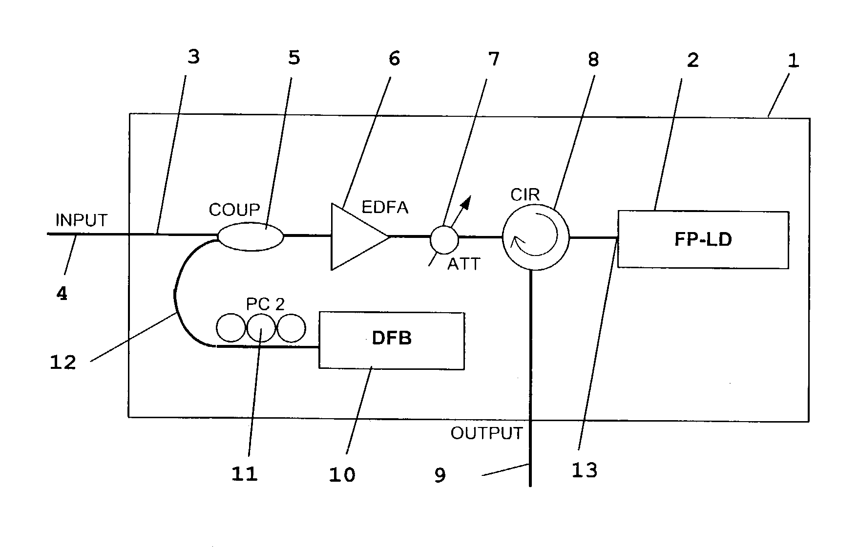
[0074]The state-of-polarization of an optical signal is stabilized by single wavelength injection-locking. The signal is injected into a laser diode with its wavelength matched to a longitudinal mode of the laser diode. The optical signal can be either in continuous wave (CW) form or in pulse mode form.

[0075]The laser diode aligns the varying states of polarization of the optical signal by acting as an intensity compensating polarizer. If the wavelength of the signal matches one of the longitudinal modes of the laser diode the transverse electric (TE) component is amplified and its intensity is stabilized while transverse magnetic (TM) components are absorbed. Thus, the laser diode functions as an intensity compensating polarizer with a transverse electric (TE) polarized output.

[0076]FIGS. 6a and 6b show the output spectra of a Fabry-Pérot laser diode (FP-LD) when injected by a TE and a TM polarized wavelength-tunable optical signal respectively. The injected signal power is −17 dBm...


PUM

PropertyMeasurementUnit
wavelengthaaaaaaaaaa
lasing wavelengthaaaaaaaaaa

Abstract

A method of controlling the state of polarization of an optical signal includes injecting the optical signal into a laser diode and matching the wavelength of the optical signal to a longitudinal mode of the laser diode. A stabilizer signal can also be injected in to the laser diode. The wavelength of the stabilizer signal is matched a first longitudinal mode of the laser diode a longitudinal mode of the laser diode to the optical signal.

Description

BACKGROUND OF THE INVENTION[0001]1. Field of the Invention[0002]The invention relates to controlling the polarization of an optical signal including data signals. In particular the invention relates to a method and apparatus for controlling the polarization state of a laser.[0003]2. Background Information[0004]Real-time polarization control of optical signals is vital for the deployment of optical communications and switching applications as well as wavelength conversion and similar applications.[0005]Current approaches for polarization control typically consist of a polarization rotation unit and a feedback control unit. The polarization rotation is implemented either electro-optically using faraday rotators, micro-electro-mechanical systems (MEMS), liquid crystal waveplates, Lithium Niobate waveguides and segments of polarization maintaining (PM) fibers or thermal-optically using polymer waveguides. These devices, however, cannot control a rapidly varying State of Polarization (SO...

Claims


Application Information

Patent Timeline
Patent Type & Authority Patents(United States)
IPC IPC(8): H01S3/098H01S3/10G02F1/01
CPCG02F1/0136
Inventor WAI, PING-KONG ALEXANDERTAM, HWA YAWCHAN, LAI YIN SIMONCHUNG, WENG HONG
Owner THE HONG KONG POLYTECHNIC UNIV
Why Eureka
Try Eureka