Drum brake

a technology of drum brakes and struts, which is applied in the direction of brake types, slack adjusters, braking elements, etc., can solve the problems of dragging and inability to move, and the brake shoes in an extreme situation may actually remain, so as to increase the length of the extendible member, the effect of reducing the width of the strut, and reducing the slack

Inactive Publication Date: 2007-02-20
ROBERT BOSCH CORP
View PDF16 Cites 7 Cited by
  • Summary
  • Abstract
  • Description
  • Claims
  • Application Information

AI Technical Summary

Benefits of technology

[0004]A primary object of the present invention is to provide a drum brake having an extendable strut that is adjustable to control running clearance with means to prevent over adjustment when the drum brake experiences a predetermined temperature.
[0005]According to this invention, the drum brake has a hydraulic actuator that engages a first web of a first brake shoe and a second web of a second brake shoe. An extendible member that is located between the first web and the second web is extendable to define a minimum running clearance in the rest position between friction pads associated with the first and second brake shoes and the rotatable member (brake drum). A lever arm that is mounted on the first web engages a tooth on a ratchet wheel on a shaft of the extendable member. A resilient member that extends between the lever to the second web urges the first and second webs into engagement with the hydraulic actuator. When an operator desires to effect a brake application, pressurized hydraulic fluid is supplied as an input to the hydraulic actuator for developing an actuation force to move the first and second brake shoes from a rest position to a position where the corresponding friction pads thereon engage a rotatable member to effect the brake application. As the first web moves through the running clearance, the lever arm pivots with respect to the first web. When the running clearance reaches a predetermined maximum gap, the lever pivots sufficiently to move a tooth on the ratchet wheel through an arc equal to the width of the tooth and correspondingly increase the length of the extendible member as the shaft moves out of threads on an end member of the strut secured to the first web. By extending the length of the strut the first and second shoes are moves closer to the rotatable member to thereby establish a minimum width for the running clearance between the friction pads and the rotatable member. On engagement of the friction pads with the rotatable member thermal energy is created that causes thermal expansion of the components and notably the rotatable member such that the web needs to move a distance to effect a brake application that includes the running clearance and the thermal expansion in order to effect a brake application. When the temperature resulting from the thermal energy reaches a predetermined level, the lever will have been rotated such that the face on the arm moves a tooth on the ratchet wheel to extend the width of the strut however, a coil strip of a bi-metal strip has a first end attached to an end member fixed to the second web and a second end that is located in a perpendicular alignment with the arm on the lever. When the bi-metal strip experiences a predetermined environmental temperature, the free end engages the arm on the lever and prevents engagement with a tooth on the ratchet wheel. Without engagement of the lever arm with a tooth on the ratchet wheel no adjustment occurs during the brake application and as a result a current running clearance as before the brake application is maintained and unaffected by the generated thermal energy during the brake application.
[0006]An advantage of this invention resides in a drum brake wherein the generation of thermal energy during a brake application does not affect the maintenance of a minimum running clearance between friction pads and a rotatable brake drum.

Problems solved by technology

On investigation, it was found that a cause of the over adjust is due to the level of the actuation force acting on the first and second webs to move the first and second brake shoes into engagement with the drum actually compressed the brake pads and / or distorted the structural components sufficiently to indicate a greater linear distance than actually needed to move from a position of rest to an actuation position.
Thus on termination of the actuation force, when the running clearance is over adjusted, it is possible that the brake shoes in an extreme situation may actually remain engaged with the drum.
In such an extreme situation, the brake shoes cause a drag that remains until wear has removed lining material from the brake shoes.

Method used


Image

  • Drum brake
  • Drum brake
  • Drum brake

Examples


Embodiment Construction

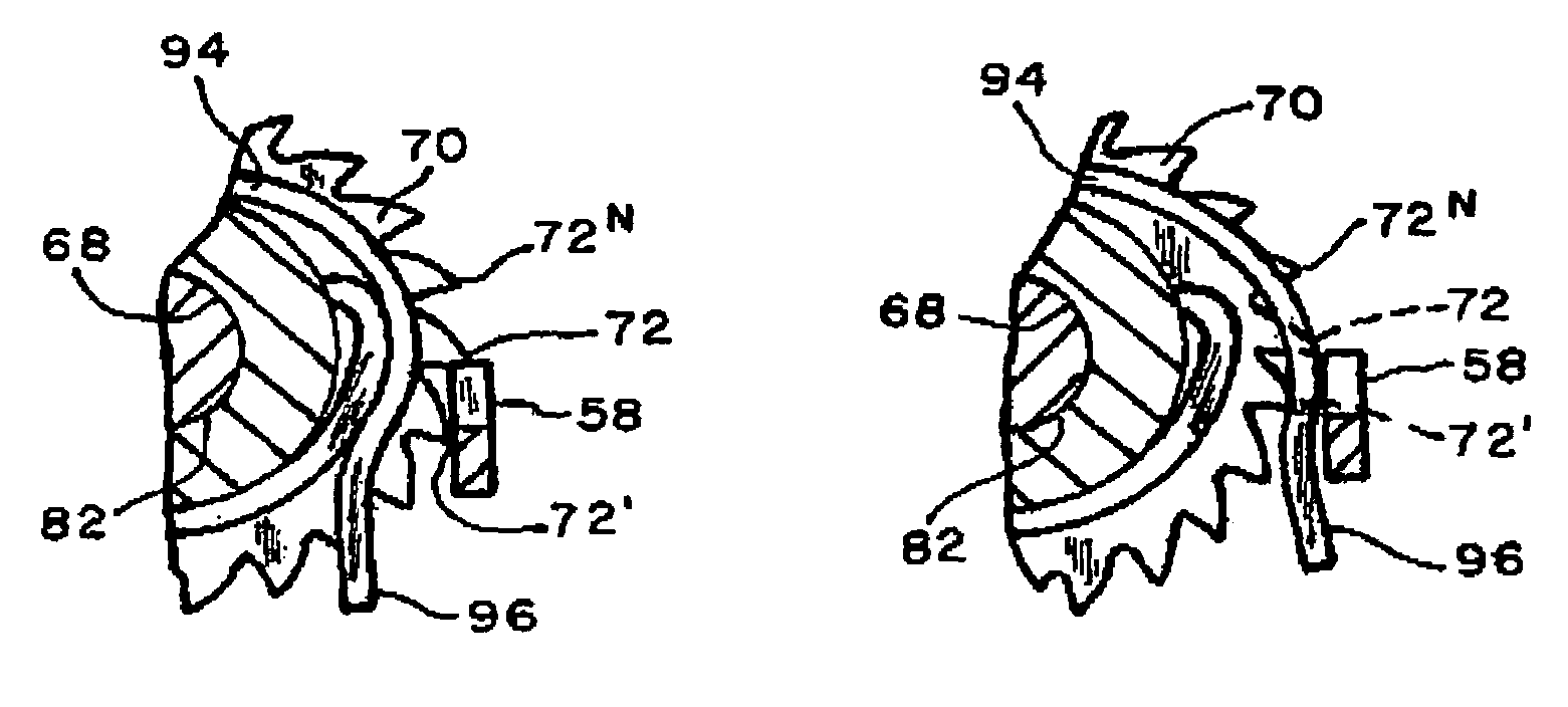
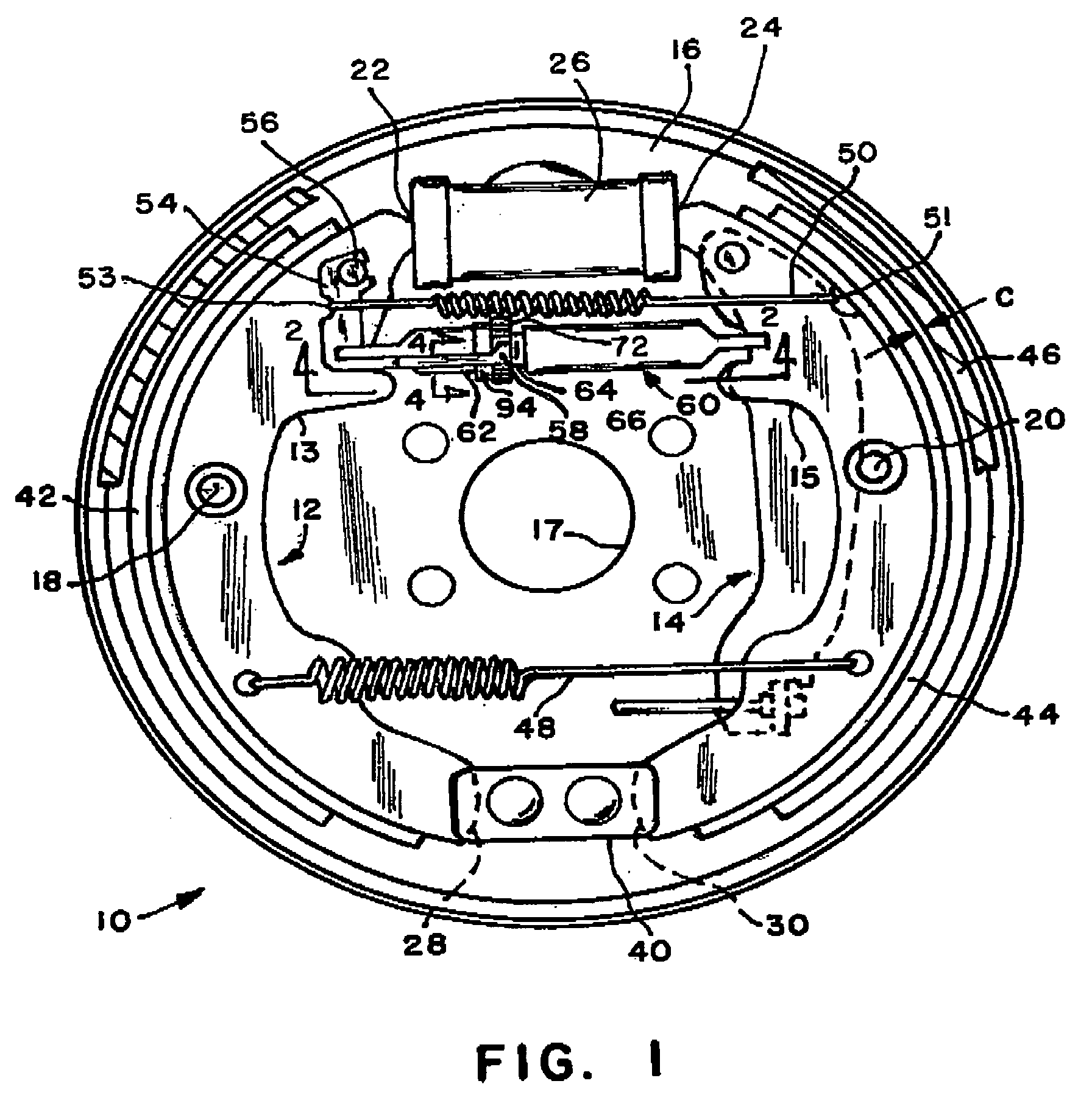
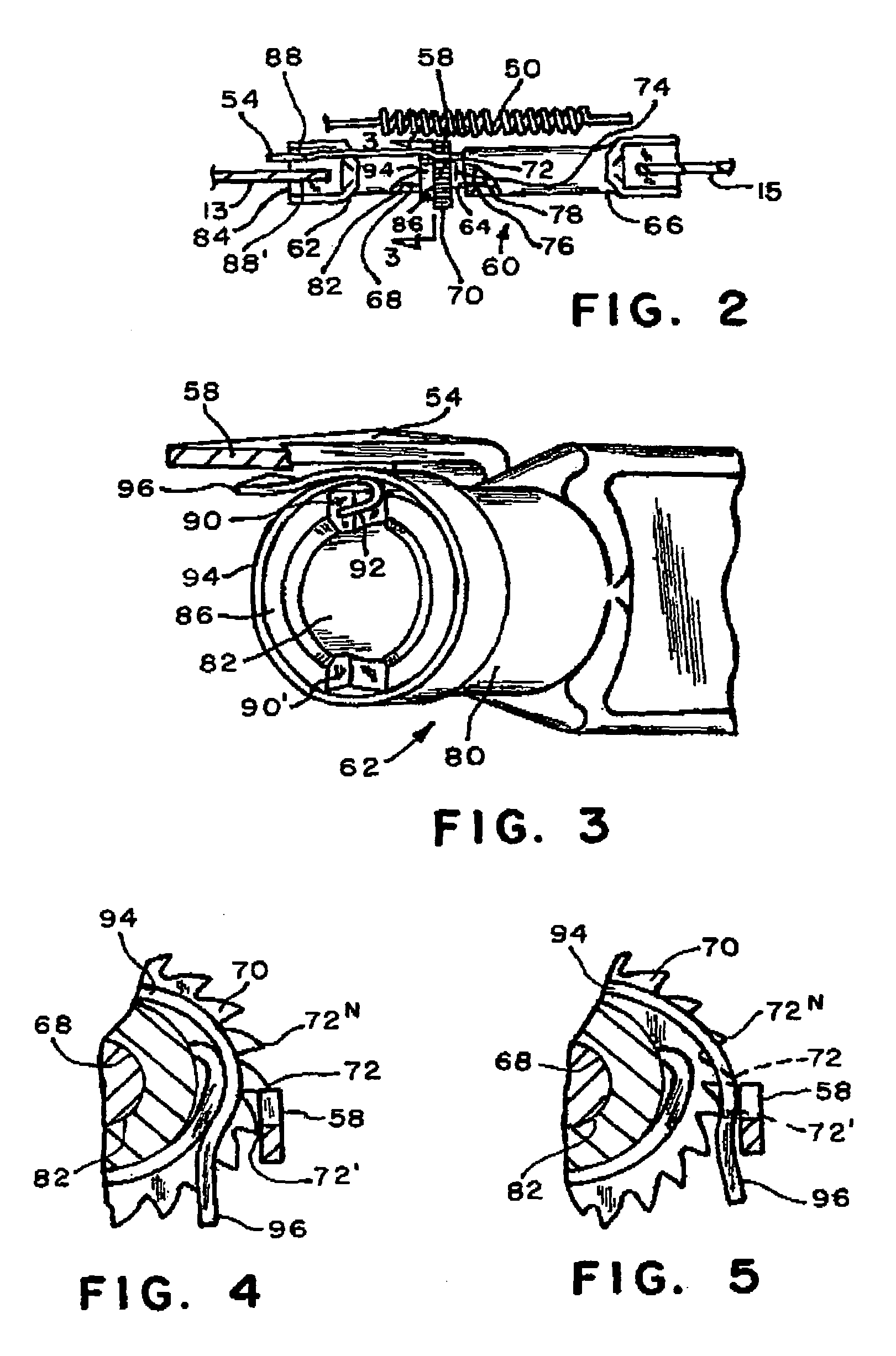
[0012]The drum brake 10 as shown in FIG. 1 includes a backing plate 16 with an opening17 for receiving an axle shaft of a vehicle. A hydraulic actuator assembly 26 is located at the top of the backing plate 16 and an anchor block 40 is aligned on the bottom of the backing plate 16. First 12 and second 14 brake shoes are retained on the backing plate 16 by first 18 and second 20 pins connected to a backing plate 16. Brake shoe 12 has a first end 22 and brake shoe 14 has a first end 24 that are respectively connected to a hydraulic actuator assembly 26. Further, brake shoe 12 has a second end 28 and brake shoes 14 has a second end 30 that are respectively connected to anchor block 40 attached to the backing plate 16. A strut 60 of a type illustrated in U.S. Pat. Nos. 4,223,765 and 4,502,574 is located between the webs 13 and 15 of brake shoes 12 and 14 respectively, to maintain a predetermined running clearance “C” between first 42 and second 44 friction pads and a drum 46. A first sp...


PUM


Abstract

An adjuster for a strut located between first and second friction members for a drum brake. The strut has a shaft that is free to rotate in a first end member and threaded into the second end member. A lever pivots during a brake application and engages a ratchet wheel on the shaft to rotates the shaft and expand the strut to maintain a minimum running clearance with respect to a rotatable member. A bi-metal coil strip that is fixed to the strut has a free end that is aligned with the lever arm. The strip responds to a predetermined temperature by moving the lever arm away from the ratchet wheel such movement of the lever does not rotate the ratchet wheel and expand the strut. Thus, on termination of a brake application a current running clearance is sustained without being affected by the predetermined temperature.

Description

[0001]This invention relates to an adjuster arrangement for a drum brake that establishes a running clearance between a friction surface and a drum and has a thermal responsive member that reacts to a predetermine temperature to terminate an adjustment function of the running clearance when a predetermined temperature occurs within the drum.BACKGROUND OF THE INVENTION[0002]Non-servo drum brakes as disclosed in U.S. Pat. Nos. 4,101,011; 4,220,227 and 4,223,765 have an extendable strut located between a first web of a first brake shoe and a second web of a second brake shoe to control a running clearance between the brake shoes and a drum. A pawl located on the first brake shoe has an arm that engages a ratchet wheel on the extendable strut to provide for an extension of the extendable strut when the running clearance reaches a maximum width. This type of structure for adjusting the running clearance functions in an adequate manner in a drum brake during a normal braking application. ...

Claims


Application Information

Patent Timeline
Patent Type & Authority Patents(United States)
IPC IPC(8): F16D65/56
CPCF16D65/566F16D65/563
Inventor CHAMAT, DJAMEL
Owner ROBERT BOSCH CORP
Why Eureka
Try Eureka