Traveling crane

a technology of traveling cranes and cranes, applied in the field of traveling cranes, can solve the problems of difficult steering of cranes, difficult to drive cranes equipped with rubber tires, and correspondingly large cranes to be utilized,

Active Publication Date: 2007-02-20
LIEBHERR WERK EHINGEN
View PDF13 Cites 10 Cited by
  • Summary
  • Abstract
  • Description
  • Claims
  • Application Information

AI Technical Summary

Benefits of technology

[0008]In order to achieve an unrestricted steering motion, all contact points between the supporting device and the ground preferably lie outside the turning radius of the truck and the tracklaying gear mounted thereon. This measure makes it possible to turn the truck in the desired new driving direction without encountering obstacles. The supporting device preferably can be freely turned by 360° in an unobstructed fashion.
[0011]It is advantageous that the width of the supporting device can be adjusted transverse to the driving direction. The ground contact surface can be increased by providing the supporting device with outriggers that can be extended transverse to the driving direction and retracted for the driving mode. The supporting device preferably has outriggers that can be pivoted about an upright axis and the projecting ends of which carry legs that can be raised and lowered. The outriggers can be pivoted into an operating position and retracted into a driving position, wherein the outriggers preferably do not protrude over the total width of the truck in the driving position.
[0012]According to an additional development of the invention, the crane has a modular design with respect to the subassemblies superstructure, supporting device and truck. The respective crane can be advantageously assembled in accordance with the building block principle. A separable coupling may be provided, in particular, between the supporting device and the truck such that the supporting device with the superstructure arranged thereon can be placed onto different trucks. This would make it possible to place the crane onto a tracklaying gear with a narrower track gauge for special tasks and to utilize a conventional tracklaying gear with a normal track gauge for conventional tasks, in which a wide roadway is available.
[0013]The supporting device may contain a center part, on which several outriggers are mounted, as well as a superstructure bearing for rotatably supporting the superstructure and a truck bearing for rotatably supporting the truck. In order to achieve a modular design, the superstructure bearing preferably is realized complementary to the truck bearing, i.e., the superstructure bearing on the center part of the supporting device corresponds to the bearing that is provided on the truck and carries the center part and the superstructure, respectively. The truck bearing on the center part of the supporting device corresponds to the bearing provided on the superstructure. The complimentary design, of the superstructure bearing and the truck bearing on the central part of the supporting device makes it possible to directly place the superstructure onto the truck. If the supporting device is not needed, it can be removed and the superstructure and the truck can be directly connected to one another. It is advantageous to provide separable rapid-action couplings between the superstructure and the supporting device on one hand and between the supporting device and the truck on the other hand in order to shorten the conversion process.

Problems solved by technology

If significant hoisting heights need to be reached and it is required to lift comparatively heavy loads, a correspondingly large crane needs to be utilized which is difficult to maneuver with a tracklaying gear that has such a narrow track gauge.
It is usually not possible to drive a crane equipped with rubber tires while its equipment is in the upright position, namely because the soft rubber tires do not ensure a sufficient lateral stability.
However, tracklaying gears with very small track gauges make it very difficult to steer the crane because the distance between the tracks is so small that the crane can no longer be steered by decelerating one track or by driving both tracks in opposite directions.

Method used


Image

  • Traveling crane
  • Traveling crane
  • Traveling crane

Examples


Embodiment Construction

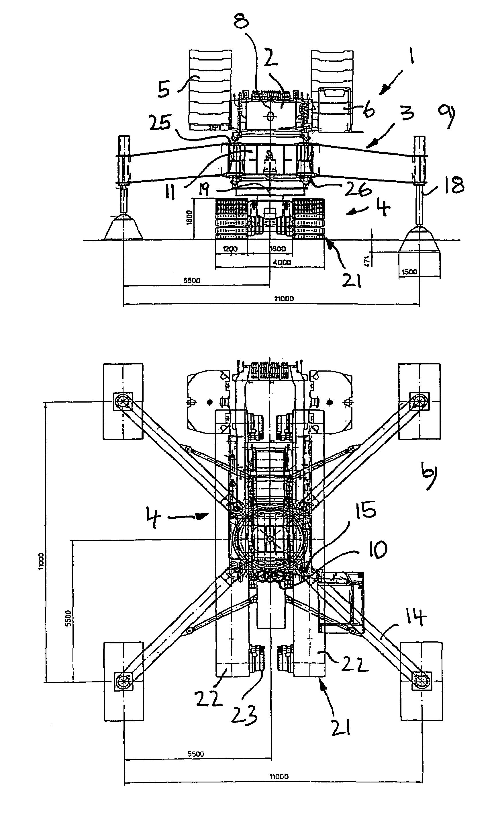
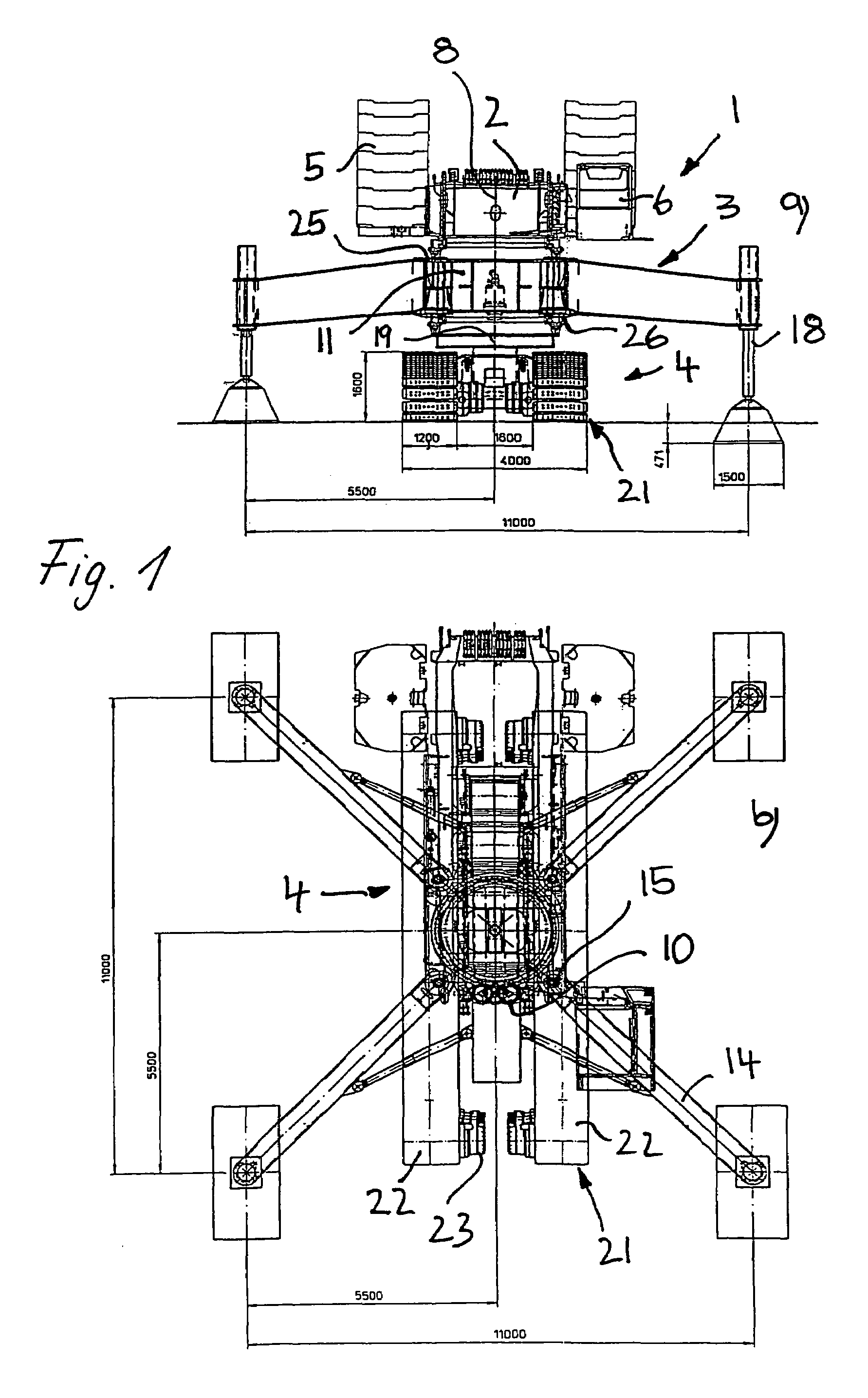
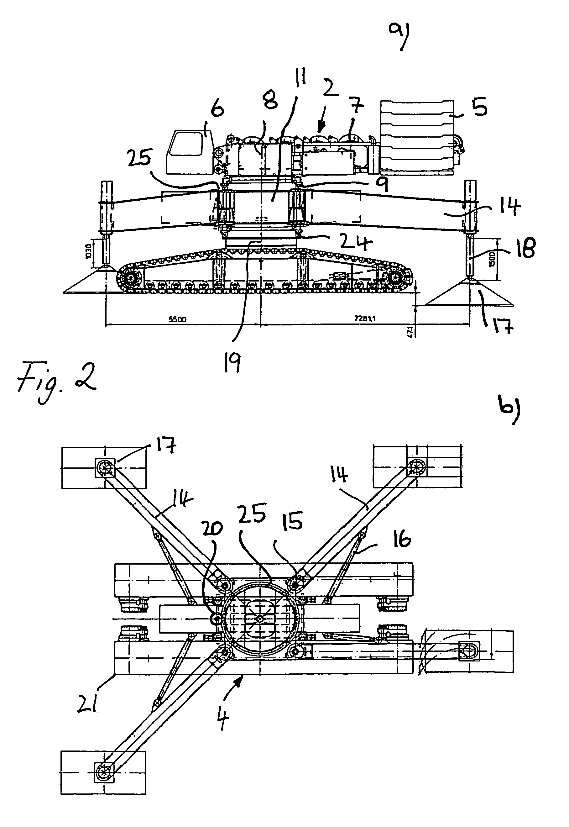
[0026]The traveling crane 1 shown in FIGS. 1–3 comprises a superstructure 2, a supporting device 3 and a truck 4.

[0027]The superstructure 2 comprises a not-shown crane jib with hoisting means that may be realized in the form of a telescopic jib that is able to derrick about a horizontal axis. The superstructure 2 also comprises ballast means 5, a driver's cabin 6 and various drive assemblies 7, e.g., a hoisting mechanism with a corresponding drive or a derricking cylinder with a corresponding hydraulic drive for setting the crane jib upright.

[0028]The superstructure 2 is supported on the supporting device 3 such that it can be essentially turned about a vertical axis of rotation 8, wherein a separable rapid-action coupling 9 is provided between the superstructure 2 and the supporting device 3. The superstructure 2 can be turned relative to the supporting device 3 by means of a superstructure rotary drive 10.

[0029]According to FIGS. 1 and 2, the supporting device 3 comprises a centra...


PUM


Abstract

The invention pertains to a traveling crane consisting of a superstructure that can be turned about an upright axis and carries a crane jib with hoisting means, a truck with a tracklaying gear that carries the superstructure and a supporting device with several outriggers that can be raised and lowered, wherein the superstructure as well as the truck can be turned relative to the supporting device about an upright axis.

Description

BACKGROUND OF THE INVENTION[0001]The present invention pertains to a traveling crane consisting of a superstructure that can be turned about an upright axis and carries a crane jib with hoisting means, a truck with a tracklaying gear that carries the superstructure and a supporting device with several outriggers that can be raised and lowered.[0002]In certain applications, the respective crane used needs to be mobile and also have a very small track gauge because the roadway to be traveled by the crane only has a limited width. It occasionally occurs that a maximum width of only four meters is available. If significant hoisting heights need to be reached and it is required to lift comparatively heavy loads, a correspondingly large crane needs to be utilized which is difficult to maneuver with a tracklaying gear that has such a narrow track gauge. It is usually not possible to drive a crane equipped with rubber tires while its equipment is in the upright position, namely because the ...

Claims


Application Information

Patent Timeline
Patent Type & Authority Patents(United States)
IPC IPC(8): B66C23/80B66C23/36B66C23/16B66C23/84
CPCB66C23/84B66C23/80
Inventor WILLIM, HANS-DIETER
Owner LIEBHERR WERK EHINGEN
Why Eureka
Try Eureka