Endoscope apparatus having an internal channel

a technology of endoscope and internal channel, which is applied in the field of endoscope equipment, can solve the problems of fatigue, heavy weight of the operating portion, and large size of the main body of the operator, and achieve the effect of easy operation and good operability

Inactive Publication Date: 2007-02-20
OLYMPUS OPTICAL CO LTD
View PDF13 Cites 1210 Cited by
  • Summary
  • Abstract
  • Description
  • Claims
  • Application Information

AI Technical Summary

Benefits of technology

[0012]It is an object of the present invention to provide an endoscope apparatus with good operability, the endoscope apparatus being capable of easily carrying out bot...

Problems solved by technology

However, at the operating portion main body disclosed in U.S. Pat. No. 5,373,317, a motor or monitor for electrically driven bending is disposed, and thus, the operating portion main body is heavy in weight and is large in size, which means that an operator is easily tired.
Since the operator always supports the mass of this operating portion, he/she feels fatigue as a work time increases.
The operator s...

Method used


Image

  • Endoscope apparatus having an internal channel
  • Endoscope apparatus having an internal channel
  • Endoscope apparatus having an internal channel

Examples


first embodiment

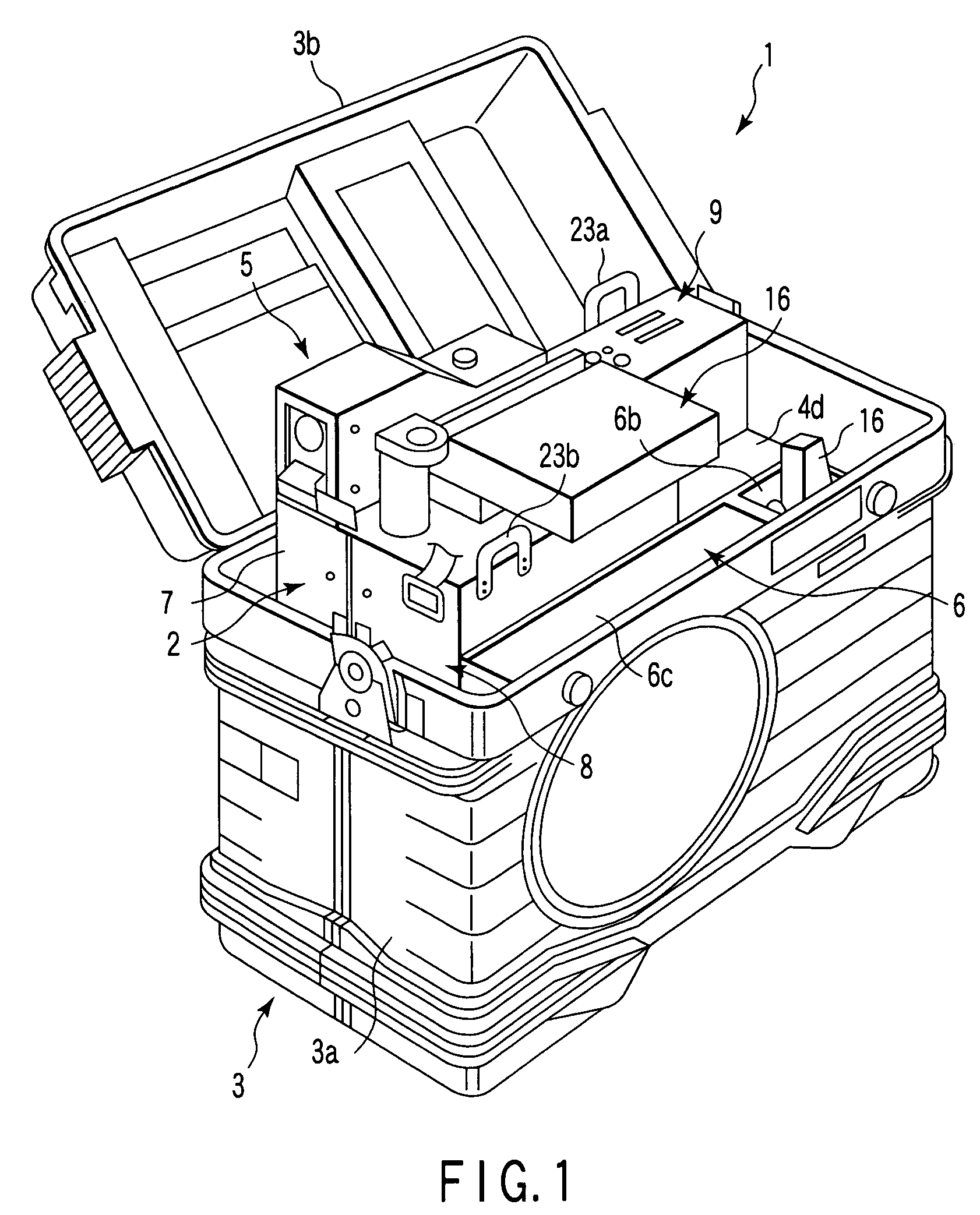
[0087]First, the present invention will be described with reference to FIGS. 1 to 14. FIG. 1 shows an endoscope apparatus 1 for industrial use according to the present invention.

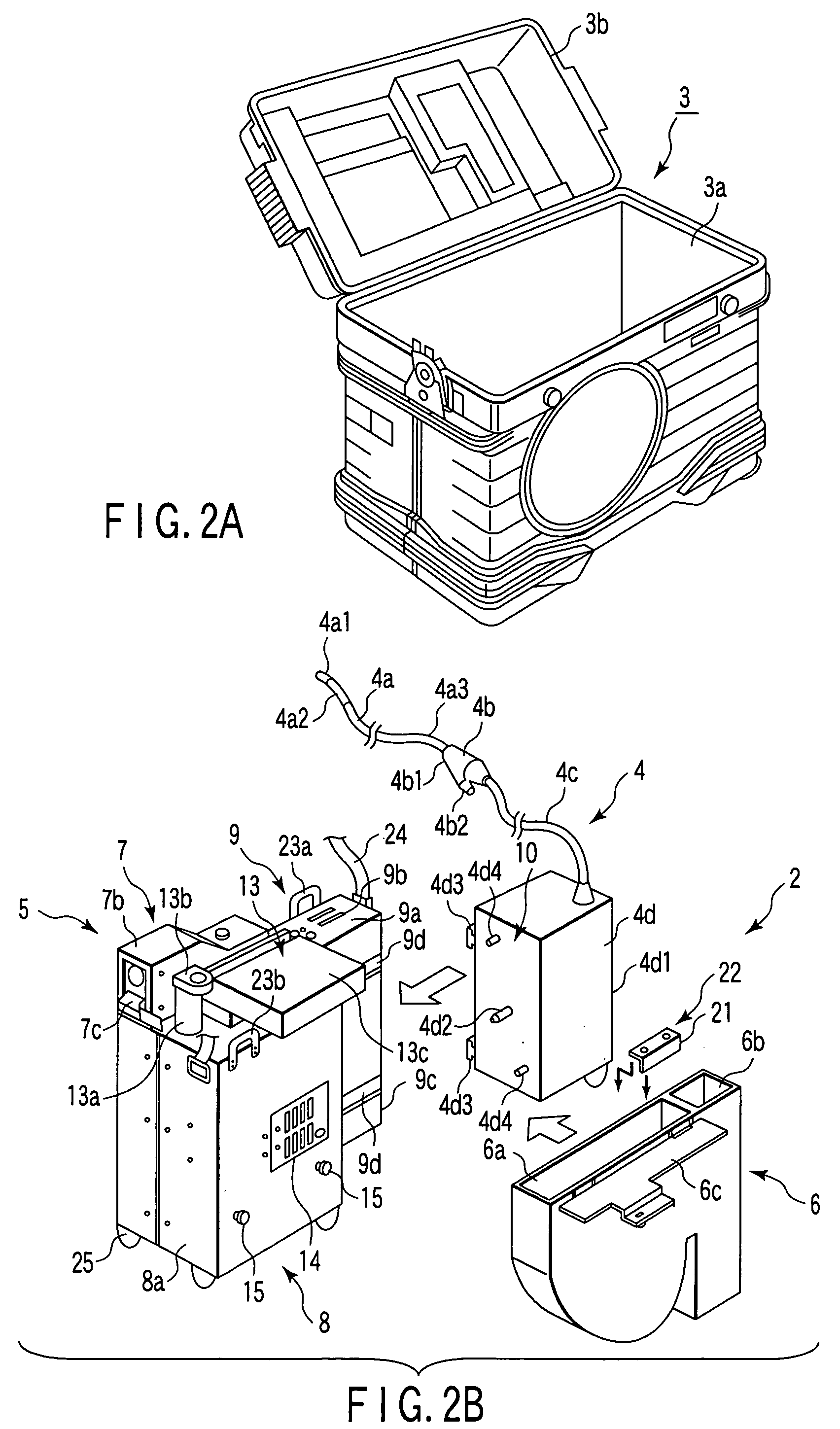
[0088]This endoscope apparatus 1 is roughly composed of: an assembling unit having constituent elements of an endoscope integrally assembled therein; and an endoscope housing case 3 for removably housing the assembling unit 2. As shown in FIG. 2A, the endoscope housing case 3 is composed of: a box-shaped case main body 3a whose top face is opened; and a lid 3b for opening and closing the top face opening. This lid 3b is turnably linked with one side part of the top face opening of the case main body 3a via a hinge portion (not shown). FIG. 1 shows a state in which the assembling unit 2 is housed in the endoscope housing case 3, and the lid 3b of the case main body 3a is opened.

[0089]FIG. 2B is an exploded perspective view showing the assembling unit 2 of the endoscope apparatus 1.

[0090]At this assembling uni...

third embodiment

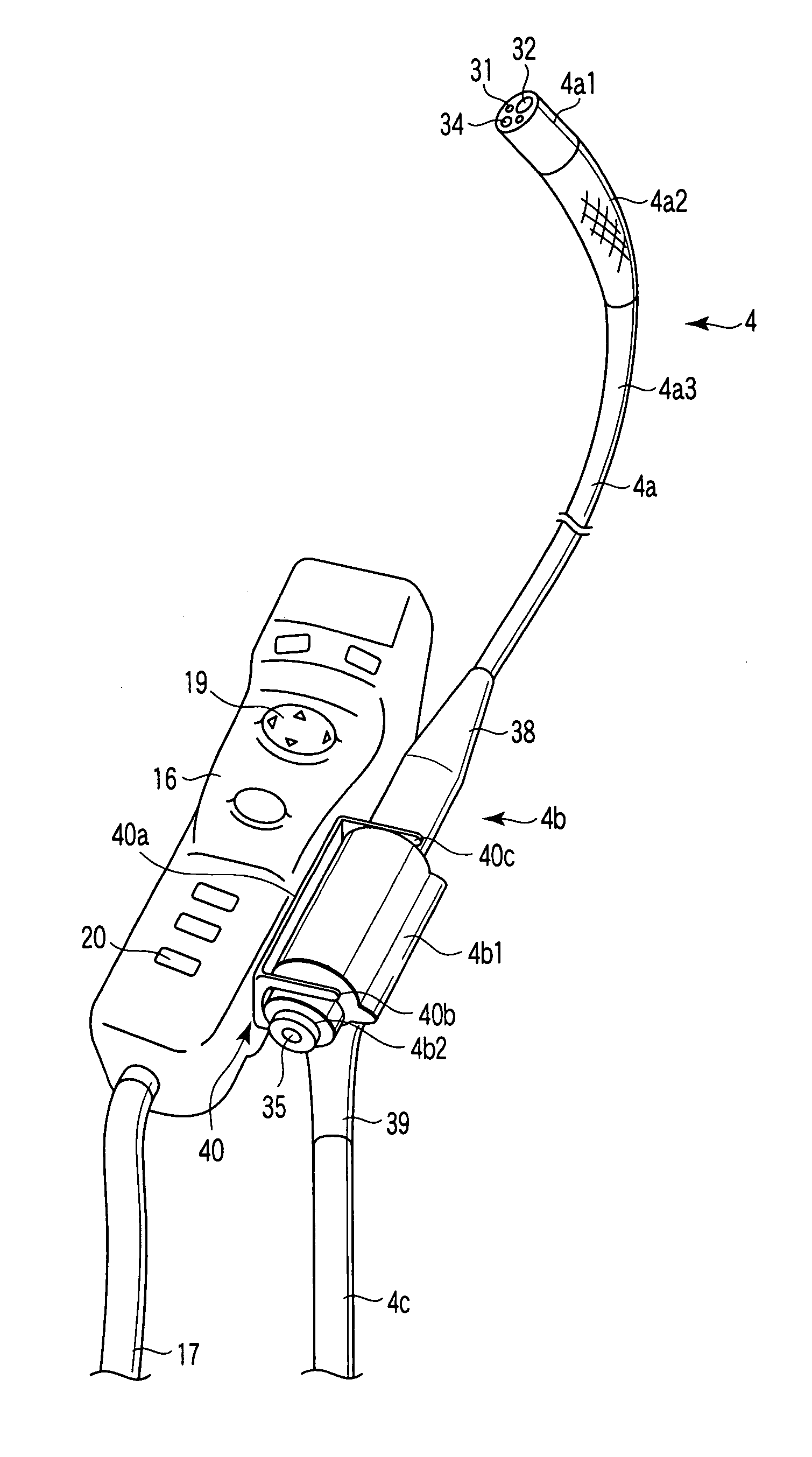
[0155]FIG. 21 shows a configuration of essential portions of an endoscope apparatus 1 for industrial use according to the present invention. In the present embodiment, a configuration of a linking portion of the intermediate linking portion 4b with the remote controller 16 has been changed.

[0156]In the present embodiment, a plurality of, for example, two attaching holes 61 are provided at one side wall part of the main body 16a of the remote controller 16. These attaching holes 61 are formed such that a large diameter hole 61a and an attaching groove 61b whose groove width is smaller than a diameter of the large diameter hole 61a are connected with each other.

[0157]Further, at a side face of a grip portion 4b1, there are provided two attaching protrusions (bolt shaped) including a top portion (slip proof portion) 62a attached with the attaching hole 61; and a body portion (attaching pin) 62b capable of passing the attaching groove 61b. These top portions 62a are attached with the at...

fourth embodiment

[0160]FIG. 22 shows a configuration of essential portions of an endoscope apparatus 1 for industrial use according to the present invention.

[0161]In the present embodiment, a configuration of the linking portion between the intermediate linking portion 4b of the scope portion 4 and the remote controller 16 has been changed as follows.

[0162]In the present embodiment, an attaching hole and an attaching protrusion which are similar to those described previously are used. For example, this configuration is such that two attaching protrusions 71 are provided at the side wall portions on both sides of the main body 16a of the remote controller 16, and attaching holes are provided respectively on both side faces of the grip portion 4b1.

[0163]In this configuration, the attaching holes and attaching protrusions are formed on both side faces of each of the main body 16a and grip portion 4b1, thus making it possible to establish a link with either of them according to the usability. Moreover, ...


PUM


Abstract

An endoscope apparatus having an internal channel comprises a scope portion in which a flexibly bending portion is provided at an elongated insert portion having a flexibility, the insert portion being inserted into a space which is a target of inspection, and a manipulating device inserting channel is formed, the channel being capable of loading therein a predetermined manipulating device which advances the inside of the insert portion to its distal end side, a remote controller which operates the flexibly bending portion by a joystick, and a connecting device which connects the scope portion and the remote controller to be integrally linked with each other at a position where an operation of the joystick and an operation for inserting the manipulating device through a proximal opening end do not interfere with each other.

Description

CROSS-REFERENCE TO RELATED APPLICATIONS[0001]This application is based upon and claims the benefit of priority from the prior Japanese Patent Application No. 2002-228936, filed Aug. 6, 2002; and No. 2003-028831, filed Feb. 5, 2003, the entire contents of which are incorporated herein by reference.BACKGROUND OF THE INVENTION[0002]The present invention relates to an endoscope apparatus mainly used in the industrial field, the endoscope apparatus being inserted into a space which is a target of inspection such as an inside of a pipe, the endoscope apparatus observing a site inside the space or an internal state thereof.[0003]In general, in an endoscope apparatus for industrial use, a frontal operating portion 160 is linked with a proximal end part of an elongated insert portion 161 to be inserted into a space which is a target of inspection such as the inside of a pipe, as shown in FIG. 47. As such an example, there is shown an exemplary configuration in which a head portion (not shown...

Claims


Application Information

Patent Timeline
IPC IPC(8): A61B1/00A61B1/018A61B1/005A61B1/05
CPCA61B1/00039A61B1/00052A61B1/00105A61B1/05A61B1/0052A61B1/018A61B1/00147A61B90/53A61B1/00042
Inventor MOTOKI, NOBUYUKIMIYAKE, KIYOSHI
Owner OLYMPUS OPTICAL CO LTD
Why Eureka
Try Eureka