
Neuromodulation device and method of using the same

a neuromodulation device and neuromodulation technology, applied in the field of deep brain stimulation, can solve the problems of increasing the risk of bleeding and damage to neural tissue, and the steering technique is limited to primarily two-dimensional steering

Active Publication Date: 2007-02-20
THE CLEVELAND CLINIC FOUND
View PDF11 Cites 230 Cited by
  • Summary
  • Abstract
  • Description
  • Claims
  • Application Information

AI Technical Summary

Benefits of technology

The patent text describes a neurostimulation device that uses a cannula and multiple leads to stimulate neural tissue. The leads can be positioned within the cannula and can be extended or retracted. The device can be used to treat deep brain stimulation (DBS) and can be designed to steer the electrical field in more than two dimensions. The technical effects of the patent text include improved accuracy in positioning the stimulation lead, reduced risk of bleeding and damage to neural tissue, and the ability to deploy multiple leads in a three-dimensional volume of tissue.

Problems solved by technology

If the lead is not properly positioned and needs to be moved, it must be removed and re-inserted thereby increasing the risk of bleeding and damage to the neural tissue.
These steering techniques, however, are limited to primarily two-dimensional steering since the electrodes are positioned in a linear or planar configuration.

Method used


Image

  • Neuromodulation device and method of using the same
  • Neuromodulation device and method of using the same
  • Neuromodulation device and method of using the same

Examples


Embodiment Construction

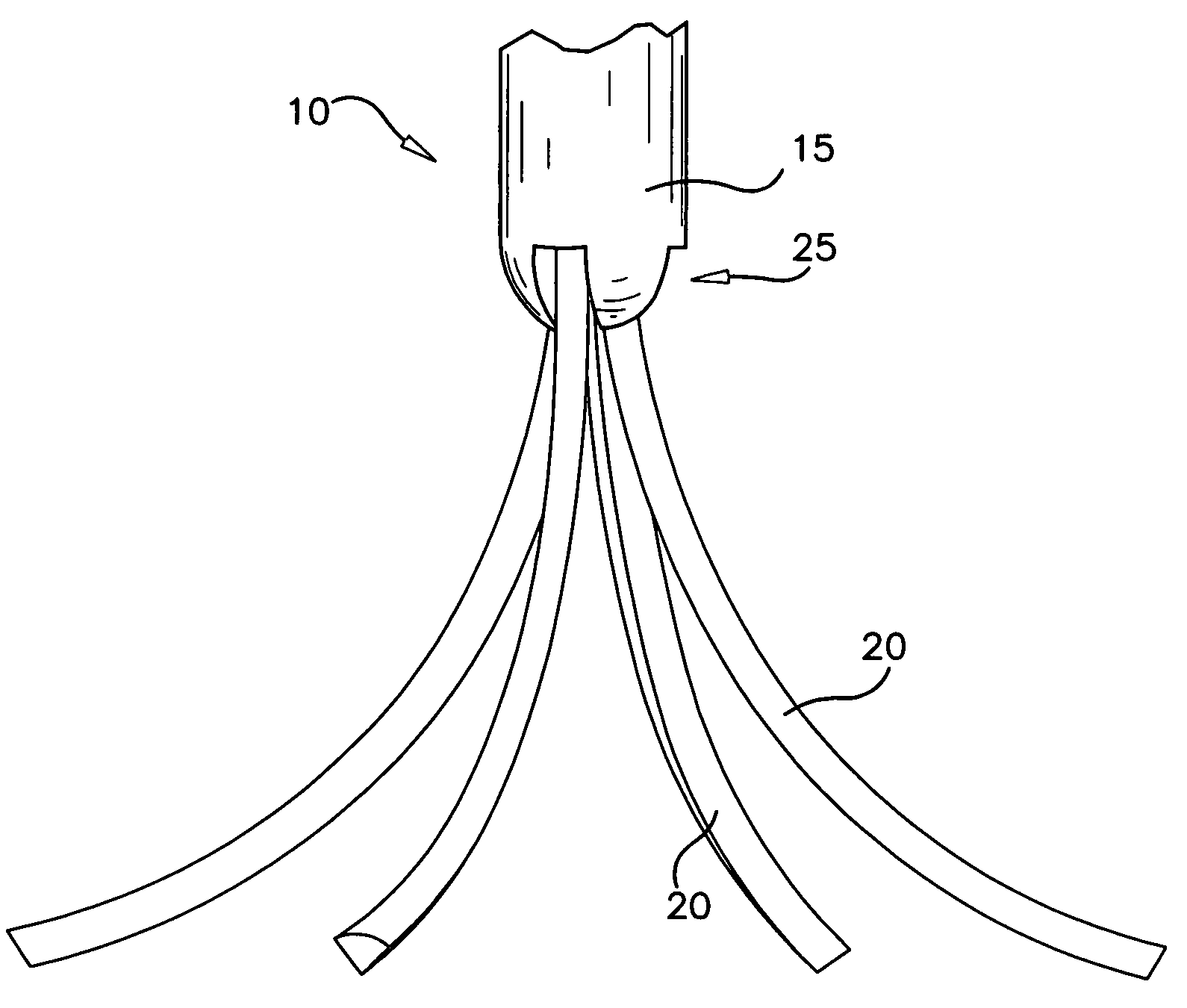
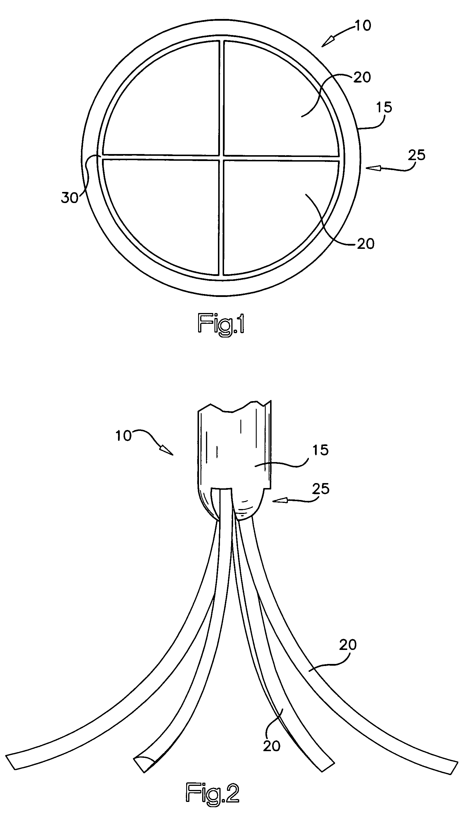
[0017]FIG. 1 illustrates a bottom view of one embodiment of a neurostimulation device 10. The neurostimulation device 10 includes a cannula 15 and a plurality of individual leads 20 constrained within a lumen of the cannula 15. The plurality of leads 20 can be movable between a retracted position (as shown in FIG. 1) and an extended position.

[0018]The cannula 15 has a proximal end (not shown) for accepting the plurality of leads 20 and a distal end 25 having an opening 30 configured to permit the leads 20 to be advanced out of the opening 30 in the cannula 15. The cannula 15 may be formed from any metal, plastic, or the like, and may be electrically active or inactive depending on the manner in which electrical energy is to be applied.

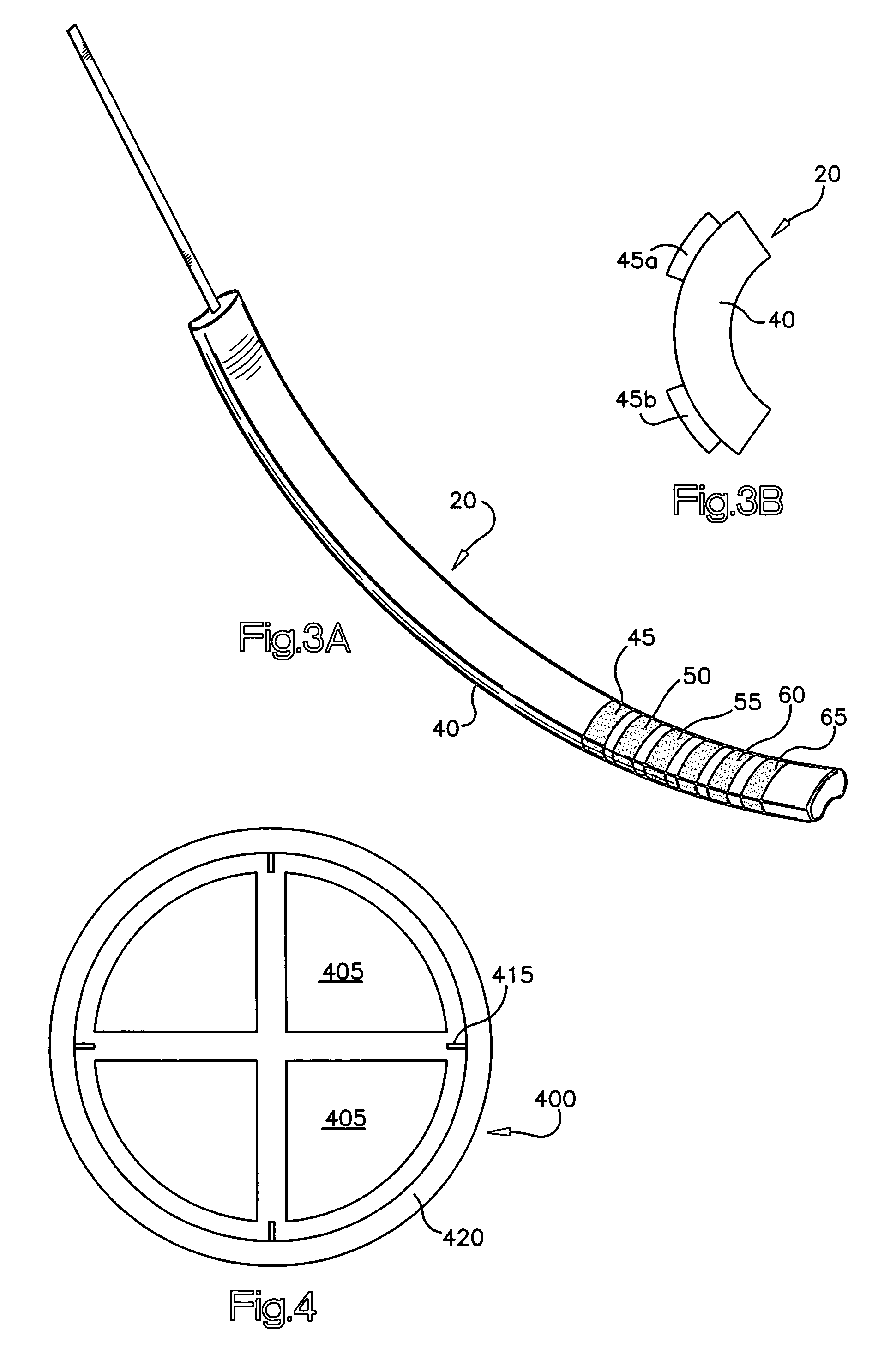
[0019]In one embodiment, each lead 20 has a “pie shaped” cross-section such that all of the leads 20 can form a circular cross-section when the leads 20 are constrained in the cannula 15. For example, each individual lead can be placed adjacent to the ...


PUM


Abstract

A device for modulating a volume of neural tissue comprising: a cannula having a proximal end, a distal end, and a lumen extending to at least the distal end, an actuator mechanism at least partially disposed in the lumen of the cannula; a plurality of leads having at least one electrode disposed thereon, the plurality of leads being coupled to the actuator mechanism to reciprocate between a retracted position wherein the plurality of leads are radially constrained within the lumen and an extended position; and a guide provided at the distal end of the cannula to deflect the plurality of leads radially outwardly into the neural tissue when the actuator mechanism is moved to the extended position.

Description

REFERENCE TO RELATED APPLICATIONS[0001]This application claims priority to U.S. Provisional Application Nos. 60 / 391,260 and 60 / 391,261 both filed Jun. 24, 2002, which are both incorporated by reference in their entireties.BACKGROUND OF THE INVENTION[0002]In the case of deep brain stimulation (DBS), it is particularly critical that the stimulation lead be properly positioned. If the lead is not properly positioned and needs to be moved, it must be removed and re-inserted thereby increasing the risk of bleeding and damage to the neural tissue. It is therefore desirable to place the lead within the brain in one attempt and avoid subsequent movement or repositioning of the lead.[0003]These steering techniques, however, are limited to primarily two-dimensional steering since the electrodes are positioned in a linear or planar configuration. In the case of deep brain stimulation (DBS), the stimulation treatment requires stimulation of a volume of neural tissue. Since the exact location of...

Claims


Application Information

Patent Timeline
Patent Type & Authority Patents(United States)
IPC IPC(8): A61N1/04
CPCA61N1/0534A61N1/0529
Inventor REZAI, ALI R.HALL, JOHN D.KUBAN, BARRY D.BAKER, KEN
Owner THE CLEVELAND CLINIC FOUND
Learn More