Method and system for configuring parameters for flash memory

a technology of configuring parameters and flash memory, applied in the field can solve the problems of not being able to meet the requirements of flash memory devices, the approach is not very flexible, and the design flexibility is evident, so as to achieve the effect of high level of configurability of main parameters, time saving, and high flexibility

Active Publication Date: 2007-02-20
ATMEL CORP
View PDF21 Cites 21 Cited by
  • Summary
  • Abstract
  • Description
  • Claims
  • Application Information

AI Technical Summary

Benefits of technology

[0013]The present invention provides an architecture that introduces a high level of configurability for main parameters used in flash memory devices. Configurations of all the dynamically changing design parameters are handled without affecting process code stored in the ROM. The invention thus allows higher flexibility in the design and continuous process development of the flash memory device, and does not require ROM memory mask changes for any change of the configurations. The invention also provides simplicity and generality to the process code, and compacts the ROM process code since comparisons of fuse values and related jump instructions are not needed. This allows considerable time savings during the execution of complex flash memory operations, where efficient architecture allows configuration parameters to be easily accessed during these operations.

Problems solved by technology

Embedded operations in a flash memory device are complex, especially with regard to the generation and control of parameters such as critical analog signals, which have a very large range of values and various possible values, and require very fine control.
However, this approach tends not to be very flexible.
This solution has evident negative consequences in terms of design flexibility, since it has additional costs and has increased time to obtain new silicon for the ROM.
Thus, the process code is longer and more complex because each load of a configuration value requires the use of an additional CMP instruction to check a fuse condition, and therefore many additional CMP and jump (JMP) instructions are needed.
Further, a significant drawback in this method is that the execution of additional instructions requires additional time.
This drawback is particularly serious if the involved code branch is continuously repeated during the execution of the process code.

Method used


Image

  • Method and system for configuring parameters for flash memory
  • Method and system for configuring parameters for flash memory
  • Method and system for configuring parameters for flash memory

Examples


Embodiment Construction

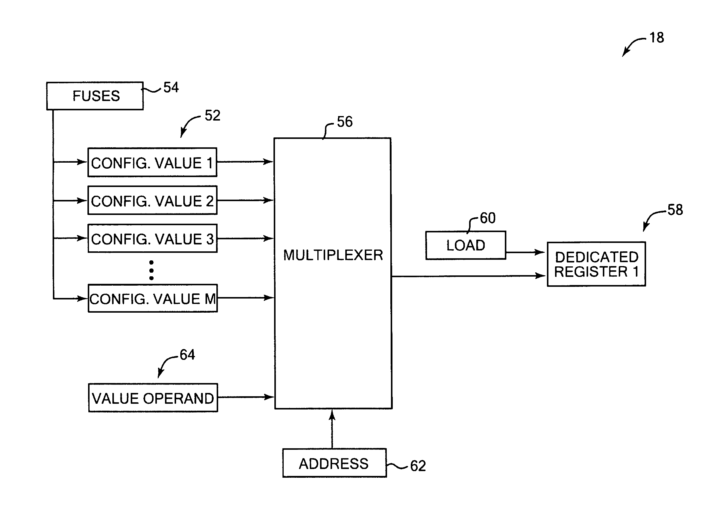
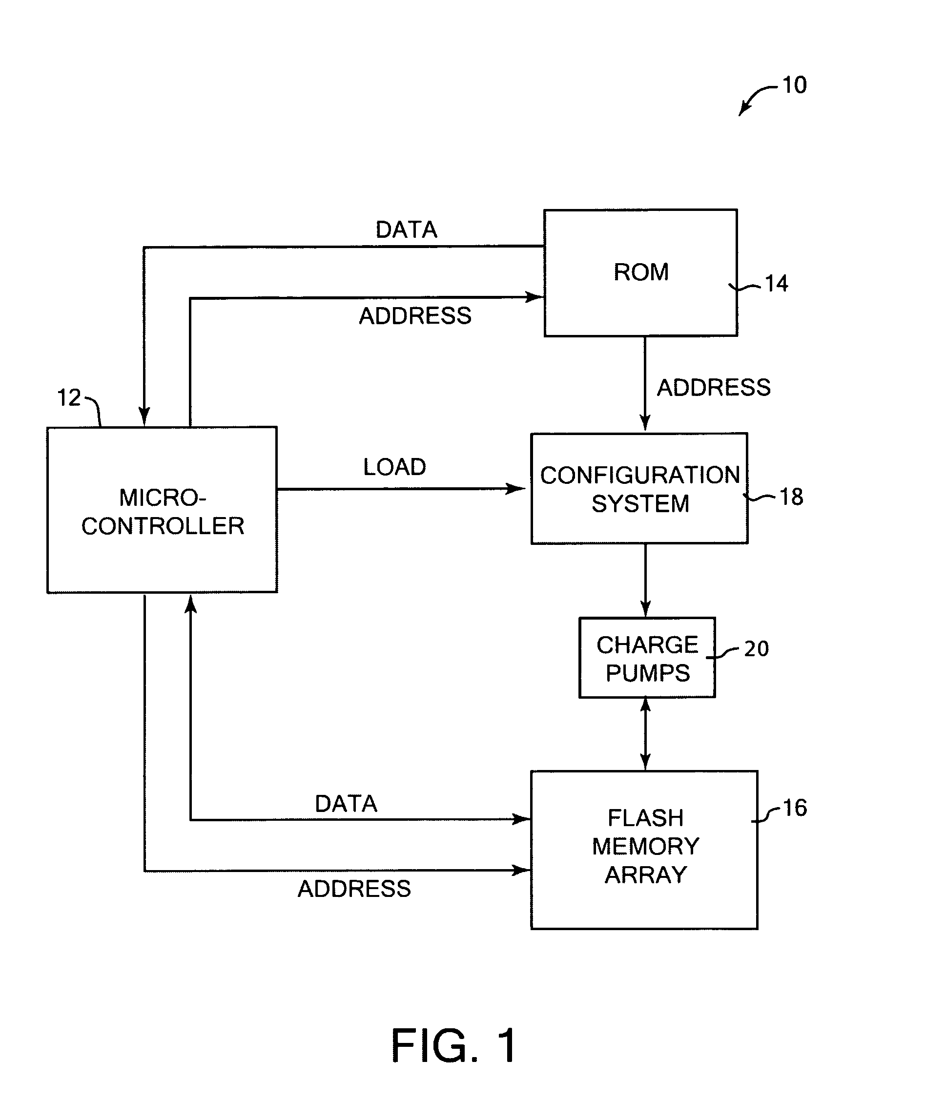
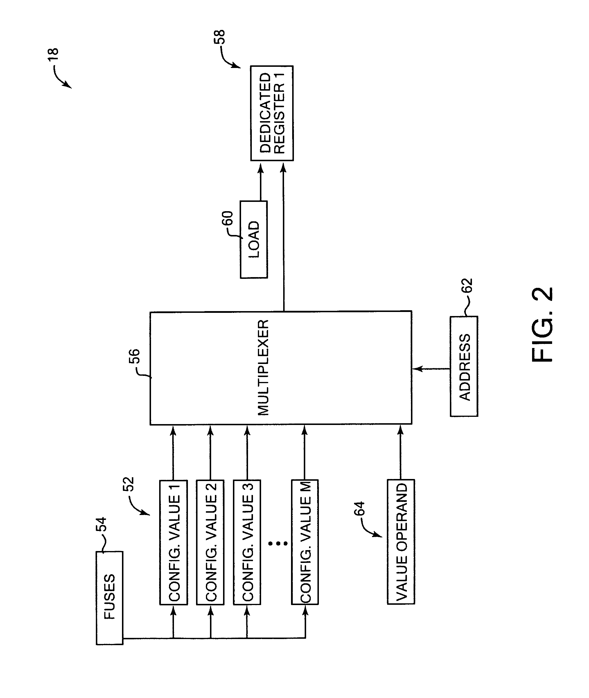
[0018]The present invention relates to flash memory devices, and more particularly to the configuring of parameters used in flash memory devices. The following description is presented to enable one of ordinary skill in the art to make and use the invention and is provided in the context of a patent application and its requirements. Various modifications to the preferred embodiment and the generic principles and features described herein will be readily apparent to those skilled in the art. Thus, the present invention is not intended to be limited to the embodiment shown but is to be accorded the widest scope consistent with the principles and features described herein.

[0019]The present invention is mainly described in terms of particular systems provided in particular implementations. However, one of ordinary skill in the art will readily recognize that this method and system will operate effectively in other implementations. For example, the processing systems and output devices u...


PUM


Abstract

Method and system for configuring parameters used in flash memory devices. A load instruction and associated address are retrieved from a read-only memory, and the address is used to select a configuration register storing a configuration value. The configuration value is loaded to an associated dedicated register to configure a parameter of the flash memory in a flash memory operation. In another aspect, one or more selected configuration values not stored in a ROM are changed if a tested flash memory operation is not within desired specifications.

Description

FIELD OF THE INVENTION[0001]The present invention relates to flash memory devices, and more particularly to the configuring of parameters used in flash memory devices.BACKGROUND OF THE INVENTION[0002]Flash memory devices are used in a wide variety of electronic devices. A flash memory device offers non-volatile storage of data, and also conveniently allows the data to be programmed into the memory and erased from the memory multiple times, thus allowing a multitude of flexible applications.[0003]A flash memory device performs all its embedded operations based on the generation and control of many design parameters, such as analog signals, maximum values, timings, etc. The values of these parameters depend on digital information stored in a series of dedicated registers in the flash memory that are associated with these parameters. Recent flash memory devices have their operations, such as program and erase operations, handled by a process implemented by program instructions stored i...

Claims


Application Information

Patent Timeline
Patent Type & Authority Patents(United States)
IPC IPC(8): G06F12/00
CPCG11C16/20G11C29/021G11C29/028G11C29/02G11C16/04G11C2029/4402
Inventor SURICO, STEFANOBARTOLI, SIMONEMARSELLA, MIRELLABOSISIO, GIORGIO
Owner ATMEL CORP
Why Eureka
Try Eureka