Multi-chamber rotating valve

a multi-chamber, valve technology, applied in water supply installation, laboratory glassware, instruments, etc., can solve the problems of not being easily converted to new processes, complex fluid delivery system, system is not easily adaptable to new pre-treatment steps or fluid delivery, etc., to reduce leakage and failure of devices, reduce costs, and be more flexible

Active Publication Date: 2014-05-06
INTEGRATED NANO TECH INC
View PDF18 Cites 12 Cited by
  • Summary
  • Abstract
  • Description
  • Claims
  • Application Information

AI Technical Summary

Benefits of technology

[0009]The use of a rotating design allows for a single plunger to draw and push fluid samples without the need for a complex valve system to open and close at various times. This greatly reduces potential for leaks and failure of the device. Furthermore, the use of a plunger allows for greater configurability in adjusting the amount of fluid drawn.
[0010]The reservoir insert is injected molded allowing for varied configurations with minimal costs. The exterior of the reservoir insert is cylindrical to allow free rotation about its axis when encased in the cartridge body. The interior section of the reservoir insert can be modified to include any size or shape reservoir or pre-treatment chamber.
[0011]Customized rotating valves retain the same exterior shape and dimensions and can be inserted into existing equipment. The processing protocol of the instrument is easily modified to account for any new chambers, sample sizes, processing times, or port locations.
[0012]The rotating valve can be stored in position leaving all ports and vents closed allowing for long-term storage and shipping of the rotating valve with liquid and solid reagents loaded within the valve.

Problems solved by technology

As the number of fluids and pre-treatment steps increase the more complex the fluid delivery system becomes.
Present designs for fluid delivery systems are customized for a particular process and are not easily converted to new processes.
These systems are not easily adaptable to new pre-treatment steps or fluid delivery without changing both the chambers and delivery procedure.

Method used


Image

  • Multi-chamber rotating valve
  • Multi-chamber rotating valve
  • Multi-chamber rotating valve

Examples


Embodiment Construction

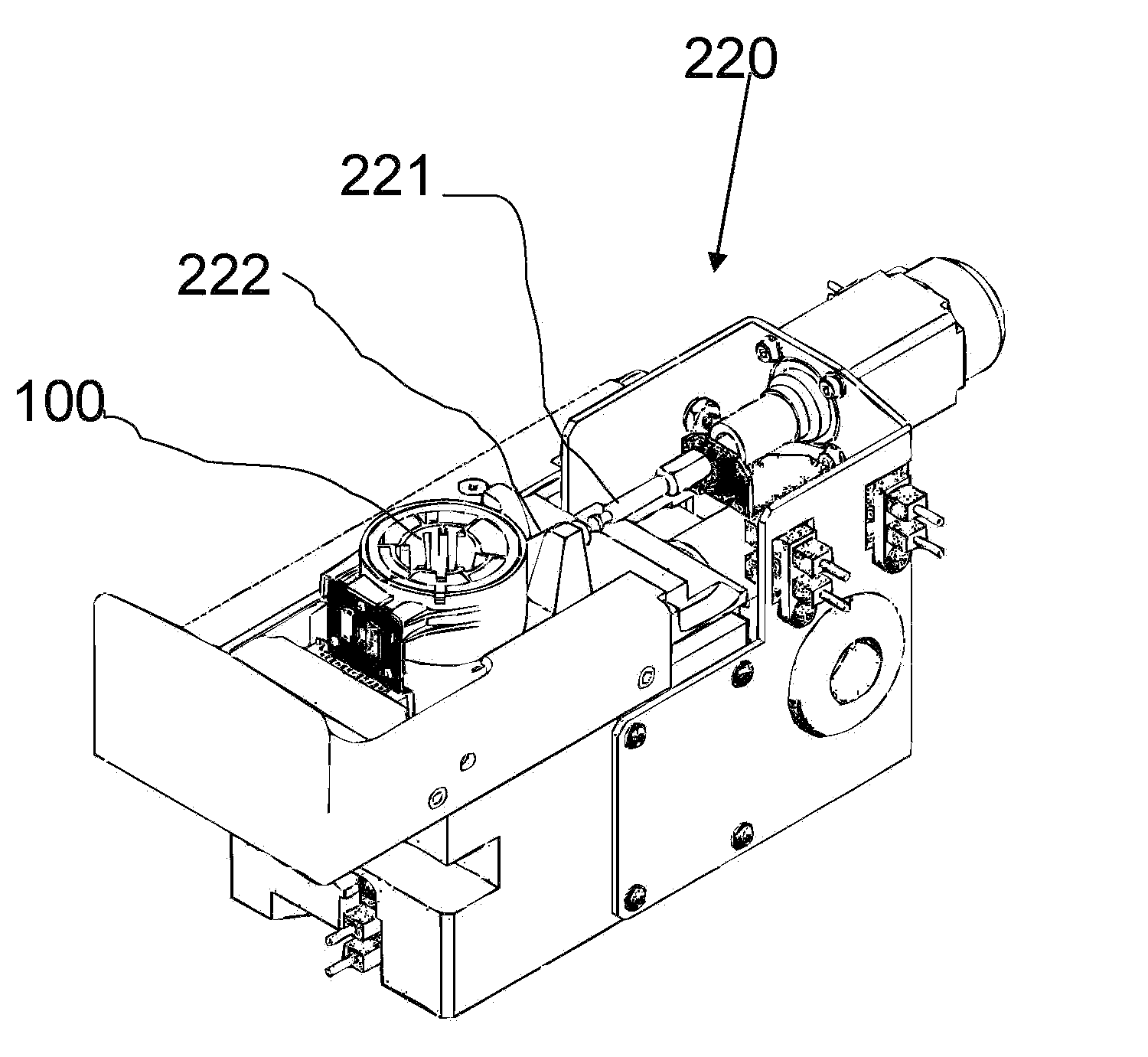
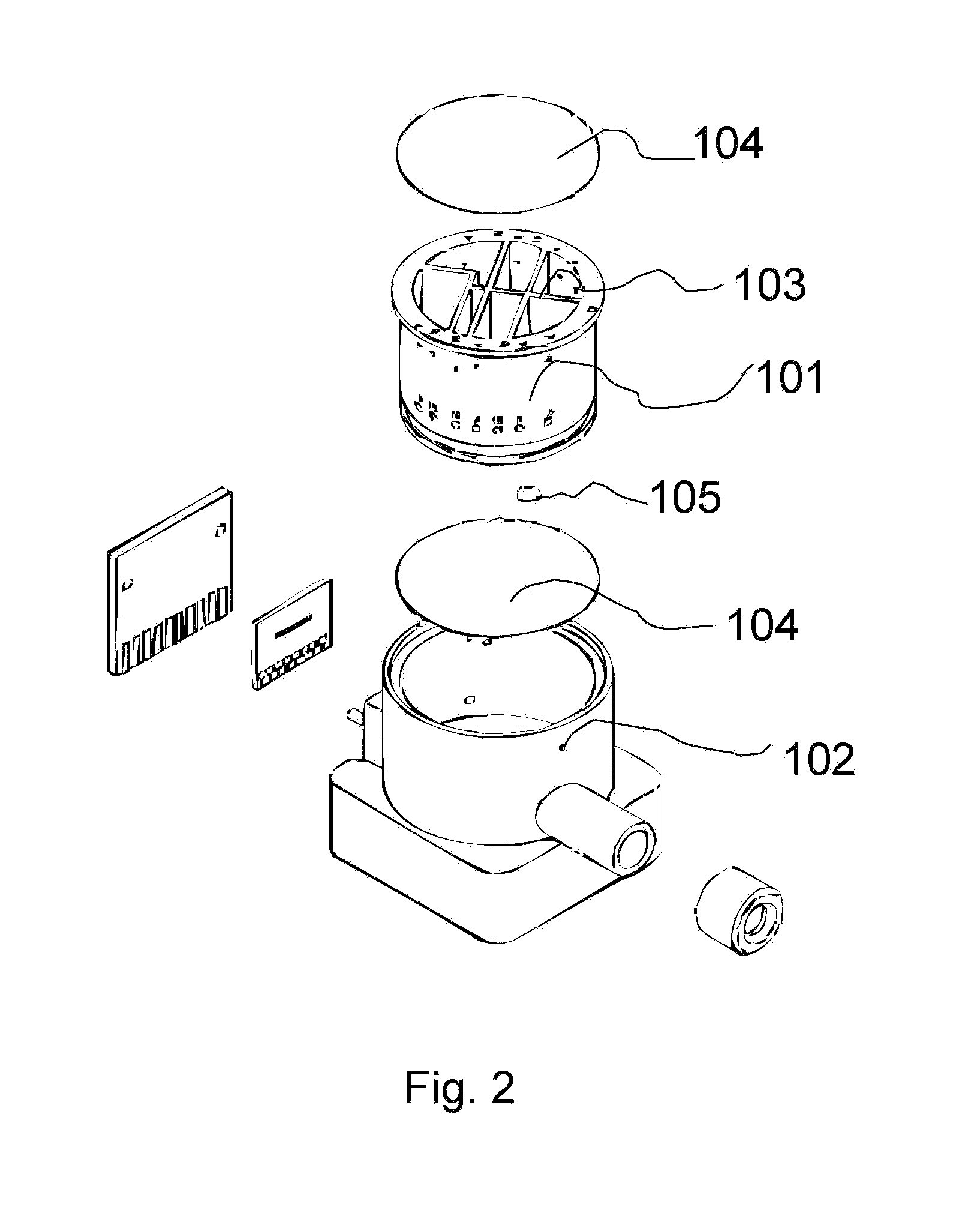
[0032]The rotating valve of the instant invention is a two piece construction capable of various positioning to allow the passage of fluid contained in the reservoirs into the fluid paths. The two piece design allows for easy manufacturing and assembly. The design further allows for the rotating valve to be a disposable piece in instruments requiring a plurality of fluids. In one embodiment, the rotating valve is a single use piece for use in detection devices. The rotating valve contains the necessary fluids for biological testing and further is capable of being injected with a field sample.

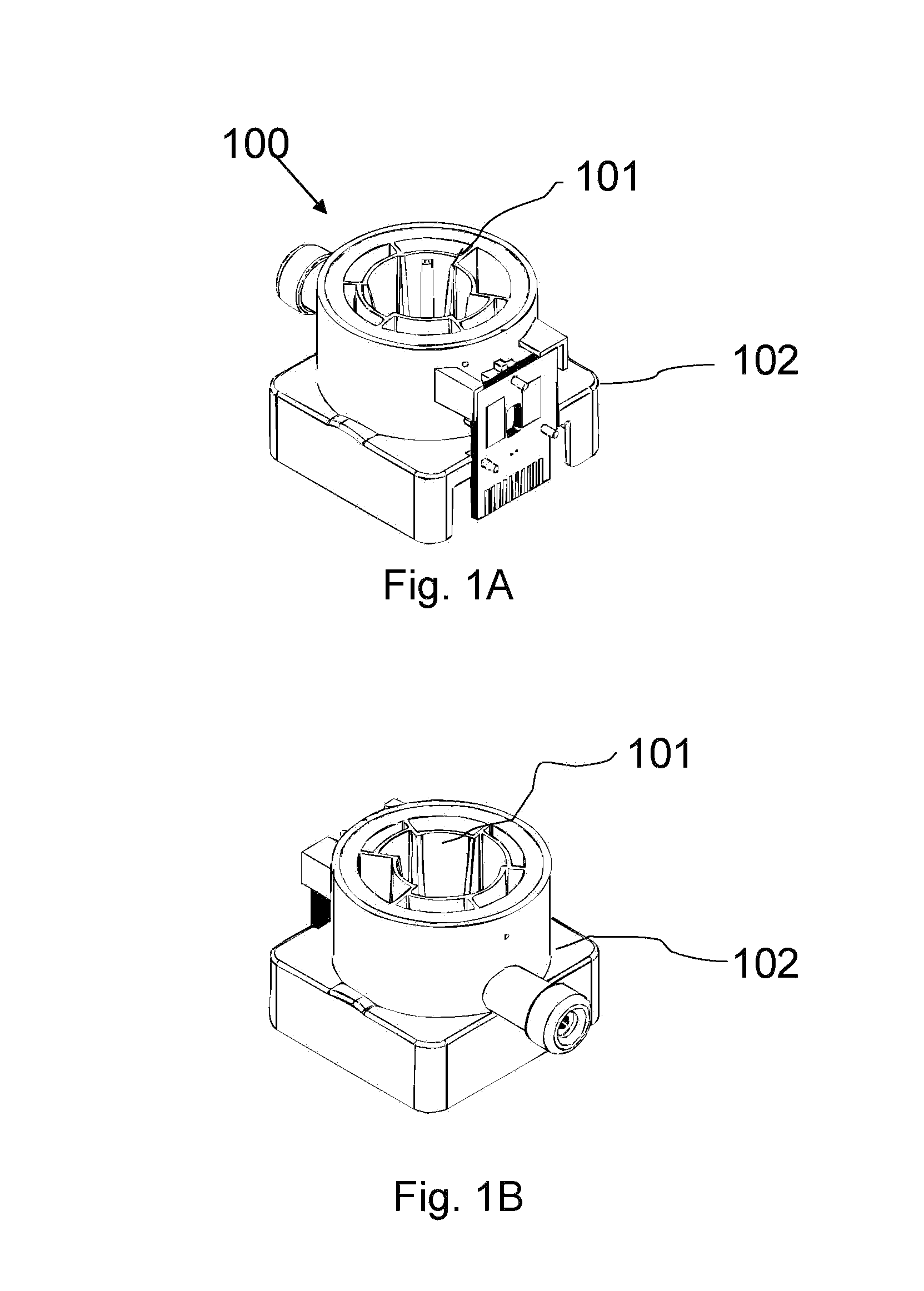
[0033]Referring to FIGS. 1A-1B there is shown an assembled rotating valve of the instant invention. The rotating valve comprises two main components. The reservoir insert 101 is contained within the cartridge body 102. The rotating valve 100 is a disposable component containing a plurality reservoirs capable of storing a plurality of fluids. In one embodiment, the reservoir insert 101 and the ca...


PUM

PropertyMeasurementUnit
distanceaaaaaaaaaa
magnetic fieldaaaaaaaaaa
areaaaaaaaaaaa

Abstract

A fluid delivery system having a rotating reservoir insert and a cartridge body. The rotating reservoir insert having a plurality of reservoirs in communication with ports on the external surface of the insert. The ports are positioned such that upon rotation the port is in-line with a fluid extracting device, such as a syringe, capable of extracting fluid from the reservoir.

Description

CROSS-REFERENCE TO RELATED APPLICATIONS[0001]This application claims priority from U.S. Provisional Patent Application Ser. No. 61 / 166,519, filed Apr. 3, 2009, the contents of which are incorporated in their entirety by reference.FIELD OF THE INVENTION[0002]The present invention relates to multi-chamber valves, and more particularly to multi-chamber rotating valves. The invention further relates to a method for transmitting a plurality of fluids from storage reservoirs to a reaction chamber.BACKGROUND OF THE INVENTION[0003]Fluid analysis generally requires a series of process steps. Theses process steps generally require that distinct fluids contact a reaction area at different times and in varying secession. Furthermore, each fluid may require different pre-treatment prior to contacting the reaction area such as chemical, optical, thermal, mechanical, magnetic or acoustical pre-treatment steps. A single fluid sample may be subjected to a variety of pre-treatment steps prior to cont...

Claims


Application Information

Patent Timeline
Patent Type & Authority Patents(United States)
IPC IPC(8): B05B7/00C12M3/00C12M1/34C12M1/00F16K31/00
CPCB01L3/567B01L2400/0622B01L3/527B01L3/0293B01L2200/16F16K11/085B01L2400/0644G01N35/1097Y10T137/86863Y10T137/8593Y10T137/0318
Inventor KILCOIN, CHRISTOPHERAPTEKAREV, KONSTANTINMURANTE, RICHARD S.CONNOLLY, DENNIS M.
Owner INTEGRATED NANO TECH INC
Why Eureka
Try Eureka