Short edge management in rule based OPC

a technology of opc and short edge, applied in the field of electronic design automation software, can solve the problems of inability to precisely match the desired design, inability to accurately adjust the layout of the integrated circuit, and inability to accurately match the rule-based approach corrections, etc., to achieve the effect of lengthening the short edge segmen

Inactive Publication Date: 2007-02-20
MENTOR GRAPHICS CORP
View PDF27 Cites 44 Cited by
  • Summary
  • Abstract
  • Description
  • Claims
  • Application Information

AI Technical Summary

Benefits of technology

[0008]In one embodiment of the present invention, if the length of an edge segment, as a result of biasing, is too short as compa

Problems solved by technology

A result of the use of photolithography under these “tight” conditions is that the resulting design, notwithstanding the use of phase shift masking, does not precisely match the desired design.
The corrections r

Method used


Image

  • Short edge management in rule based OPC
  • Short edge management in rule based OPC
  • Short edge management in rule based OPC

Examples


Embodiment Construction

[0029]In the following description, various aspects of the present invention will be described. For purposes of explanation specific numbers, materials and configurations are set forth in order to provide a thorough understanding of the present invention. In some instances, well-known features are omitted or simplified in order not to obscure the present invention.

[0030]Various operations will be described as multiple discrete steps, in a manner that is most helpful in understanding the present invention, however, the order of description should not be construed as to imply that these operations are necessarily order dependent. In particular, these operations need not be performed in the order of presentation. Further, the description repeatedly uses the phrase “in one embodiment”, which ordinarily does not refer to the same embodiment, although it may.

[0031]Width and Space Based OPC

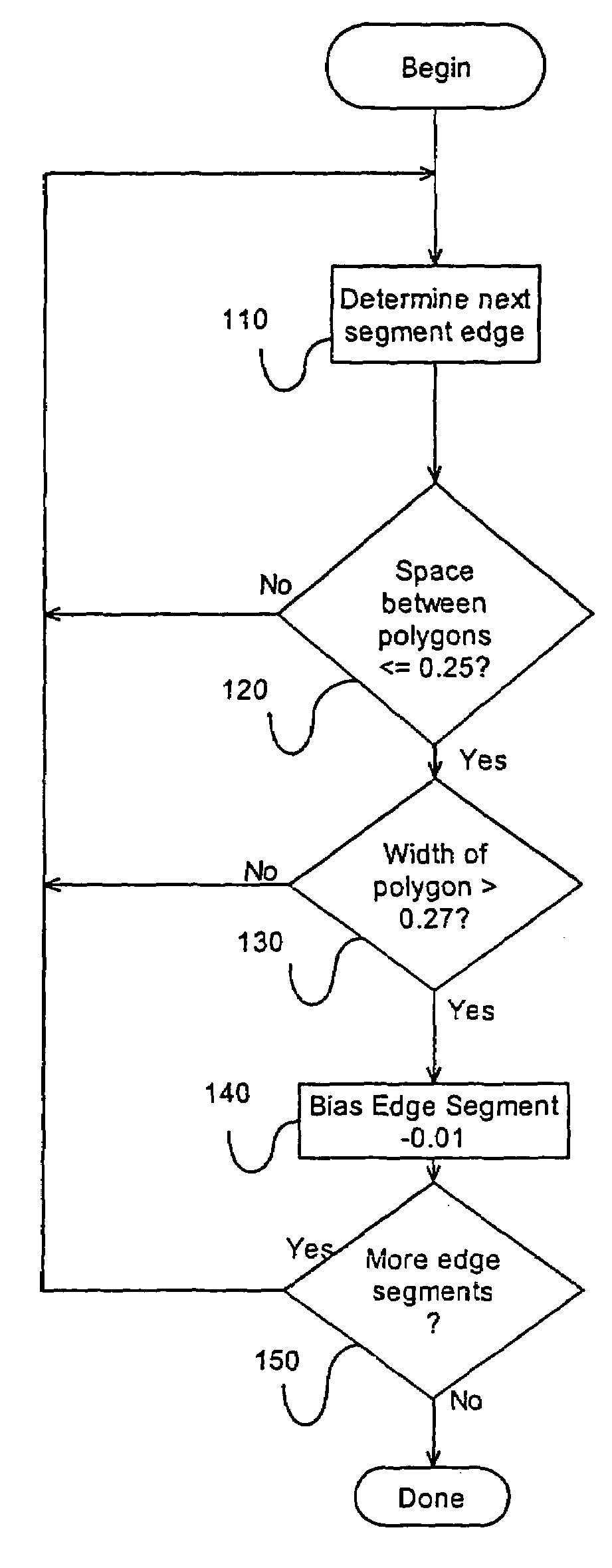
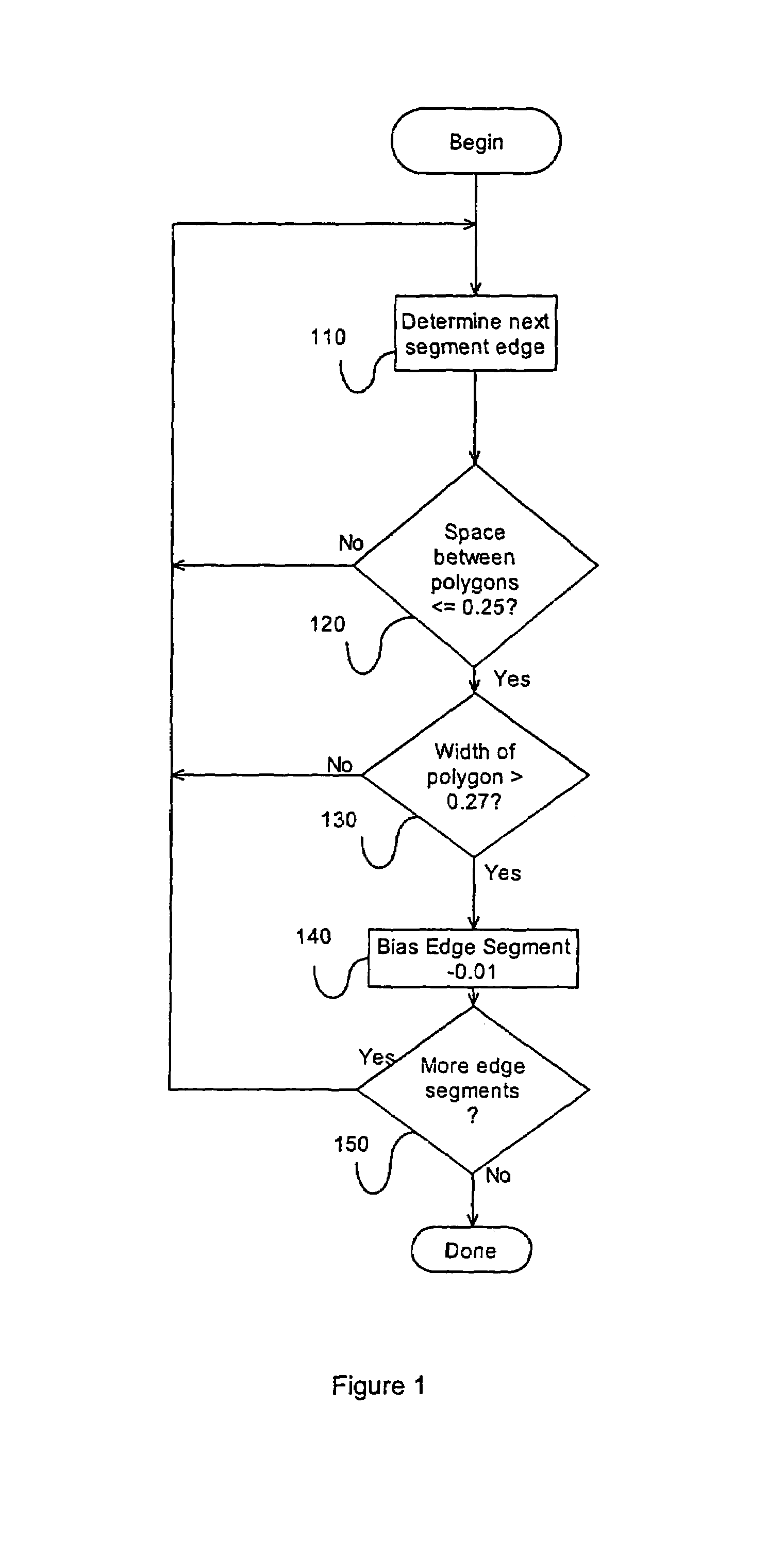
[0032]FIG. 1 shows a flowchart of a layout correction process in accordance with one embodiment of th...


PUM


Abstract

The invention discloses a method and apparatus for modifying, as appropriate, the geometries of a polygon. Based on various attributes associated with the polygon and its surroundings, modification of the location of the edge segments may conditionally occur. Additionally, if these modifications occur, a method to minimize the introduction of short edges during the modification is provided.

Description

CROSS REFERENCE TO RELATED APPLICATIONS[0001]This application is a divisional of U.S. patent application Ser. No. 10 / 402,079, filed Mar. 26, 2003, now U.S. Pat. No. 6,817,003 which is a divisional of U.S. patent application Ser. No. 09 / 882,802, filed Jun. 14, 2001, now U.S. Pat. No. 6,574,784, issued Jun. 3, 2003.FIELD OF THE INVENTION[0002]The present invention relates to the field of electronic design automation software. More specifically, the invention relates to the automatic adjustment of layout of integrated circuit designs.BACKGROUND OF THE INVENTION[0003]To be able to continually increase the gate count of semiconductor devices on fixed die size, integrated circuit (IC) designs have involved shrinking feature sizes. For the next decade, the outlook is strong for photolithography to continue to be the process by which IC are manufactured. When processing the features in today's deep sub-micron processes, the wavelength of light used in the photolithography process is less th...

Claims


Application Information

Patent Timeline
IPC IPC(8): G06F17/50G06F9/45G11C7/00
CPCG06F17/5081G06F17/5068G06F30/39G06F30/398
Inventor LIPPINCOTT, GEORGE P.SAKAJIRI, KYOHEIGRODD, LAURENCE W.
Owner MENTOR GRAPHICS CORP
Why Eureka
Try Eureka