Method and apparatus for controlling strip shape in hot rolling mills

a technology of hot rolling mills and strips, applied in the direction of rolling mill control devices, profile control devices, manufacturing tools, etc., can solve the problems of localized shape defects, shape defects, and very rapid scaling, and achieve the effect of minimizing the fixed coolant volume and effective strip shape control

Active Publication Date: 2007-02-27
NUCOR CORP
View PDF16 Cites 35 Cited by
  • Summary
  • Abstract
  • Description
  • Claims
  • Application Information

AI Technical Summary

Benefits of technology

[0007]The present invention provides a method and apparatus for localized modification of the roll gap profile to correct these types of shape defects By controlling the localized cooling of the work surface of the work roll in zones across the work roll, both the upper and lower work roll profiles can be controlled by thermal expansion or contraction of the work rolls sufficient to produce thin steel strip without pronounced shape defects and without causing localized buckling, ridges and edge wave in the strip. We have found that it is possible to change the outlying areas of the strip profile in a zone or zones across the work roll, both high areas and low areas, relative to adjacent regions, and that that can be done without causing localized buckling, ridges and edge wave in the thin strip. This is done by changing the profile of the work surface of the work roll by localized control of the cooling of a zone or zones of the work roll where the shape defect is observed relative to adjacent regions
[0045]f. a control system capable of individually regulating localized control of cooling of the work surface by cooling device(s) in each zone of the work roll so as to control the shape of the work surface and inhibit the formation of shape defects in the thin cast strip in each zone.

Problems solved by technology

If exposed to normal atmosphere, it would suffer very rapid scaling due to oxidation at such high temperatures.
Significant deviations between the incoming product profile and roll gap profile produces a localized shape defect in the outgoing rolled strip at the location across the strip width where the deviations occurs.
If the roll gap thickness is less than the incoming strip thickness in that region relative to adjacent regions across the strip width, a buckle or loose defect occurs in the strip shape in that area producing a shape defect.
If the roll gap thickness is greater than the incoming strip thickness in that region relative to adjacent regions across the strip width, a tight or ridge strip shape defect will be produced in that area of the strip.
In the course of hot mill rolling, in a cast strip plant and elsewhere, local shape defects can still occur in the strip that are not correctable by roll bending, roll force cylinder skewing or edge spraying of the strip.
Moreover, five zones, a central zone, two edge zones and two intermediate or quarter zones, can be provided, so that quarter buckles can be inhibited which is a particularly difficult problem in hot rolling.
On the other hand, if sprays from nozzles are used as the localized cooling devices, the sprays from nozzles onto the work surface should not impinge on each other because in so going the sprays can interfere with each other and reduce effective control in shaping of the work roll within a zone, and in turn reduce effective control the shape defects observed in the strip of the strip Whether the control of localized cooling is accomplished by one or more sprays or internal circulation of coolant within each zone, the coolant is typically water, although other coolants may be utilized as desired.
On the other hand, if sprays from nozzles are used as the localized cooling devices, the sprays from nozzles on the work surface should not impinge on each other, because in so going the sprays can interfere with each other and reduce effective control in shaping of the work roll within a zone, and in turn reduce effective control the shaping of defects observed in the strip of the strip.

Method used


Image

  • Method and apparatus for controlling strip shape in hot rolling mills
  • Method and apparatus for controlling strip shape in hot rolling mills
  • Method and apparatus for controlling strip shape in hot rolling mills

Examples


Embodiment Construction

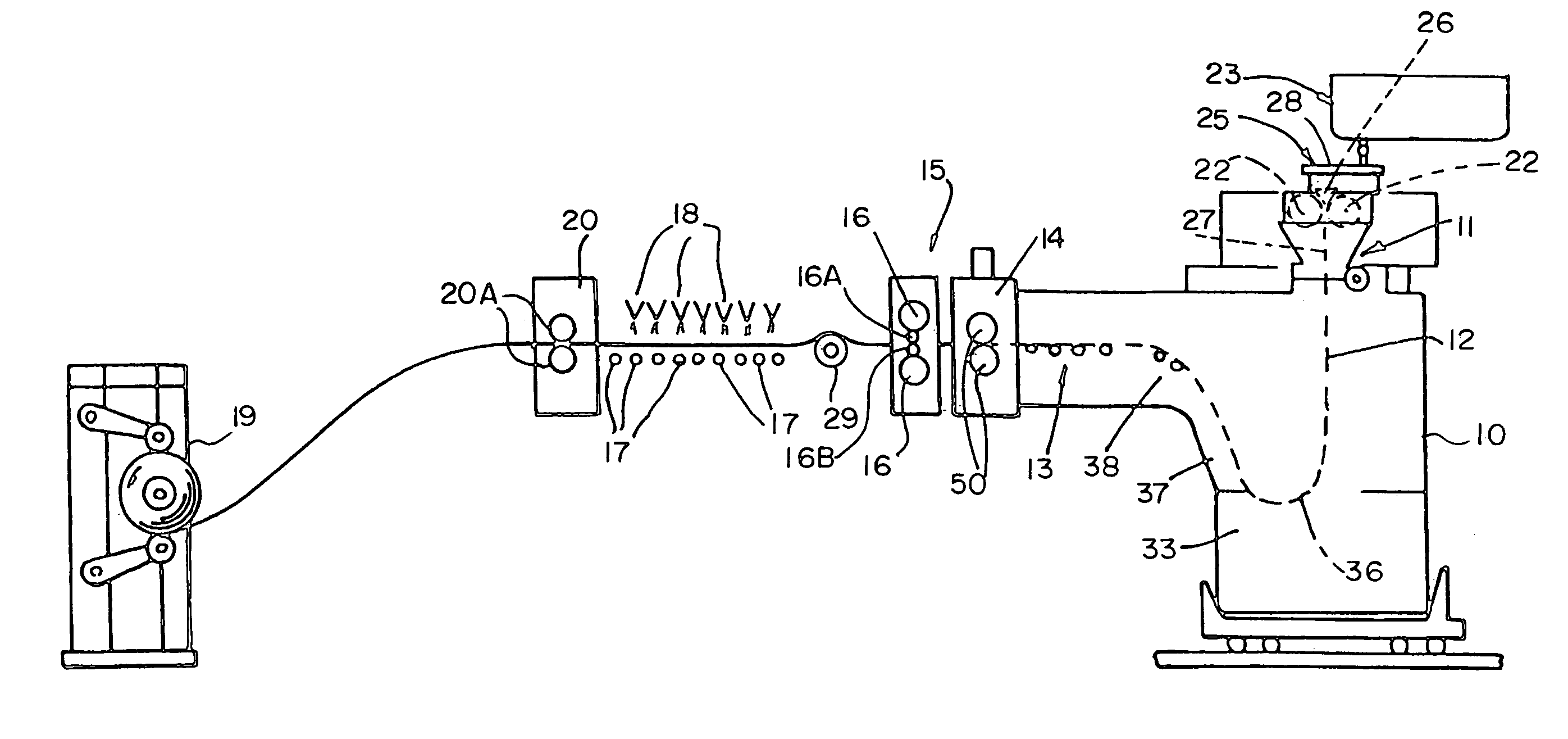
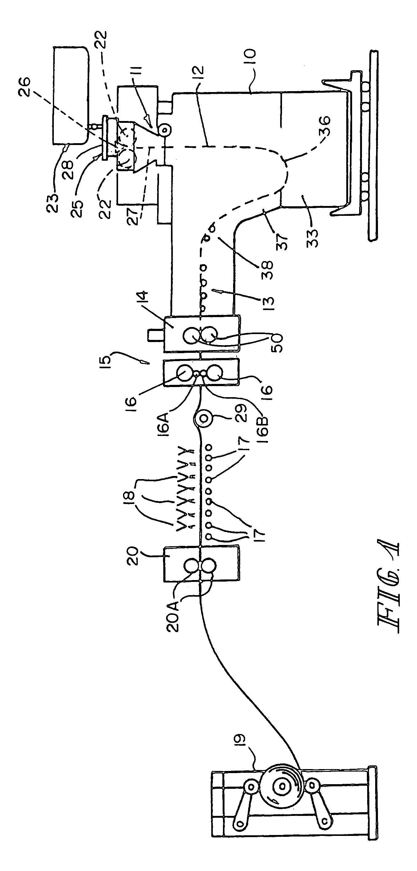
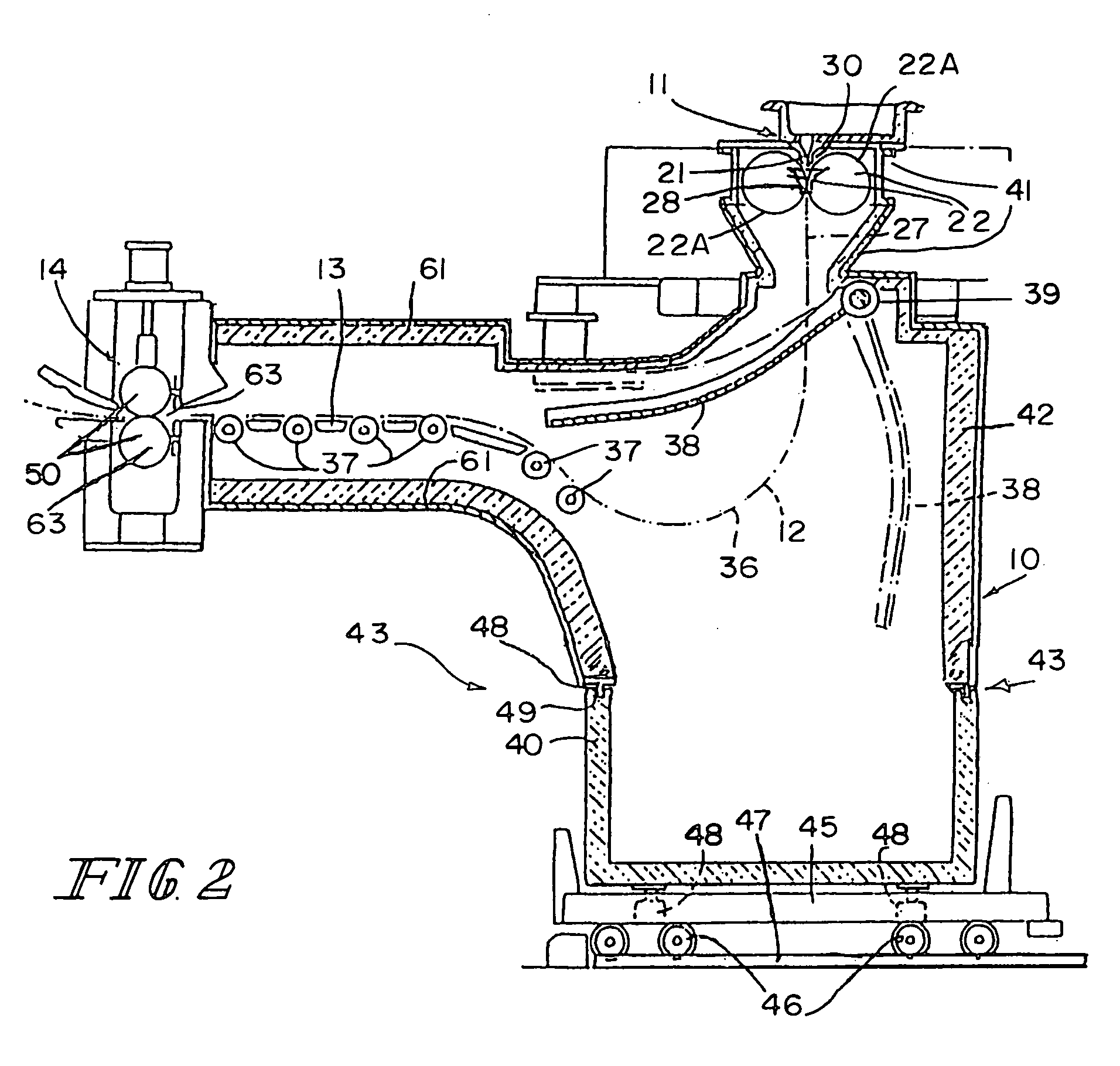
[0060]The illustrated casting and rolling installation comprises a twin-roll caster denoted generally by 11 which produces thin cast steel strip 12 which passes into a transient path across a guide table 13 to a pinch roll stand 14. After exiting the pinch roll stand 14, thin cast strip 12 passes into and through hot rolling mill 15 comprised of back up rolls 16 and upper and lower work rolls 16A and 16B, where the thickness of the strip reduced. The strip 12, upon exiting the rolling mill 16, passes onto a run out table 17 where it may be forced cooled by water jets 18, and then through pinch roll stand 20 comprising a pair of pinch rolls 20A and to a coiler 19.

[0061]Twin-roll caster 11 comprises a main machine frame 21 which supports a pair of laterally positioned casting rolls 22 having casting surfaces 22A and forming a nip 27 between them. Molten metal is supplied during a casting campaign from a ladle (not shown) to a tundish 23, through a refractory shroud 24 to a removable t...


PUM

PropertyMeasurementUnit
temperaturesaaaaaaaaaa
surface temperaturesaaaaaaaaaa
temperatureaaaaaaaaaa

Abstract

A hot rolling mill and method for operating the hot rolling mill where the shape of the strip is controlled by localized cooling devices positioned at intervals along work rolls in at least three lateral zones, a central and two edge zones, and capable of separately cooling each zone to control the shape of the work rolls in that zone and inhibit the formation of shape defects occurring in the strip being rolled. Five zones may be provided across the work surface of the work rolls so that two intermediate zones can control for quarter buckles. The hot rolling mill has particular application in continuously casting thin strip. The method can be made automatic by sensing downstream of the hot mill the shape of the strip in each zone.

Description

BACKGROUND AND SUMMARY OF THE INVENTION[0001]This invention relates to hot rolling mills and particularly to those used continuous casting of thin steel strip a twin roll caster.[0002]In a twin roll caster, molten metal is introduced between a pair of counter-rotated horizontal casting rolls which are cooled so that metal shells solidify on the moving roll surfaces, and are brought together at the nip between them to produce a solidified strip product delivered downwardly from the nip between the casting rolls. The term “nip” is used herein to refer to the general region at which the casting rolls are closest together. The molten metal may be poured from a ladle through a metal delivery system comprised of a tundish and a core nozzle located above the nip to form a casting pool of molten metal supported on the casting surfaces of the rolls above the nip and extending along the length of the nip. This casting pool is usually confined between refractory side plates or dams held in sli...

Claims


Application Information

Patent Timeline
Patent Type & Authority Patents(United States)
IPC IPC(8): B21B1/46
CPCB21B37/32B21B1/463Y10T29/49991B21B2027/103B21B37/74B21B27/10
Inventor ONDROVIC, JAY JONBRITANIK, RICHARDDOMANTI, TINOWALLACE, GLEN
Owner NUCOR CORP
Why Eureka
Try Eureka