Automatic roll data acquisition system

a data acquisition and data technology, applied in the direction of total factory control, programme control, electric programme control, etc., can solve the problems of affecting the safety of the movement of the roll may be hazardous the deformation of the roll may be dangerous to personnel working in the immediate area, so as to reduce the proximity of personnel, protect the environment, and reduce the effect of harm

Inactive Publication Date: 2005-09-08
USX CORP
View PDF19 Cites 23 Cited by
  • Summary
  • Abstract
  • Description
  • Claims
  • Application Information

AI Technical Summary

Benefits of technology

[0013] Yet another object of the present invention is to provide a means by which a receiver is moved or retracted when no roll is in position, and is thereby protected from harm due to the movement of large, heavy rolls into position on a roll grindin

Problems solved by technology

A roll is placed in service in a rolling mill for a period of time, eventually becoming deformed through wear.
The rolls are massive pieces, and the movement of the rolls may be hazardous to personnel working in the immediate area, such as when the ro

Method used


Image

  • Automatic roll data acquisition system
  • Automatic roll data acquisition system
  • Automatic roll data acquisition system

Examples


Embodiment Construction

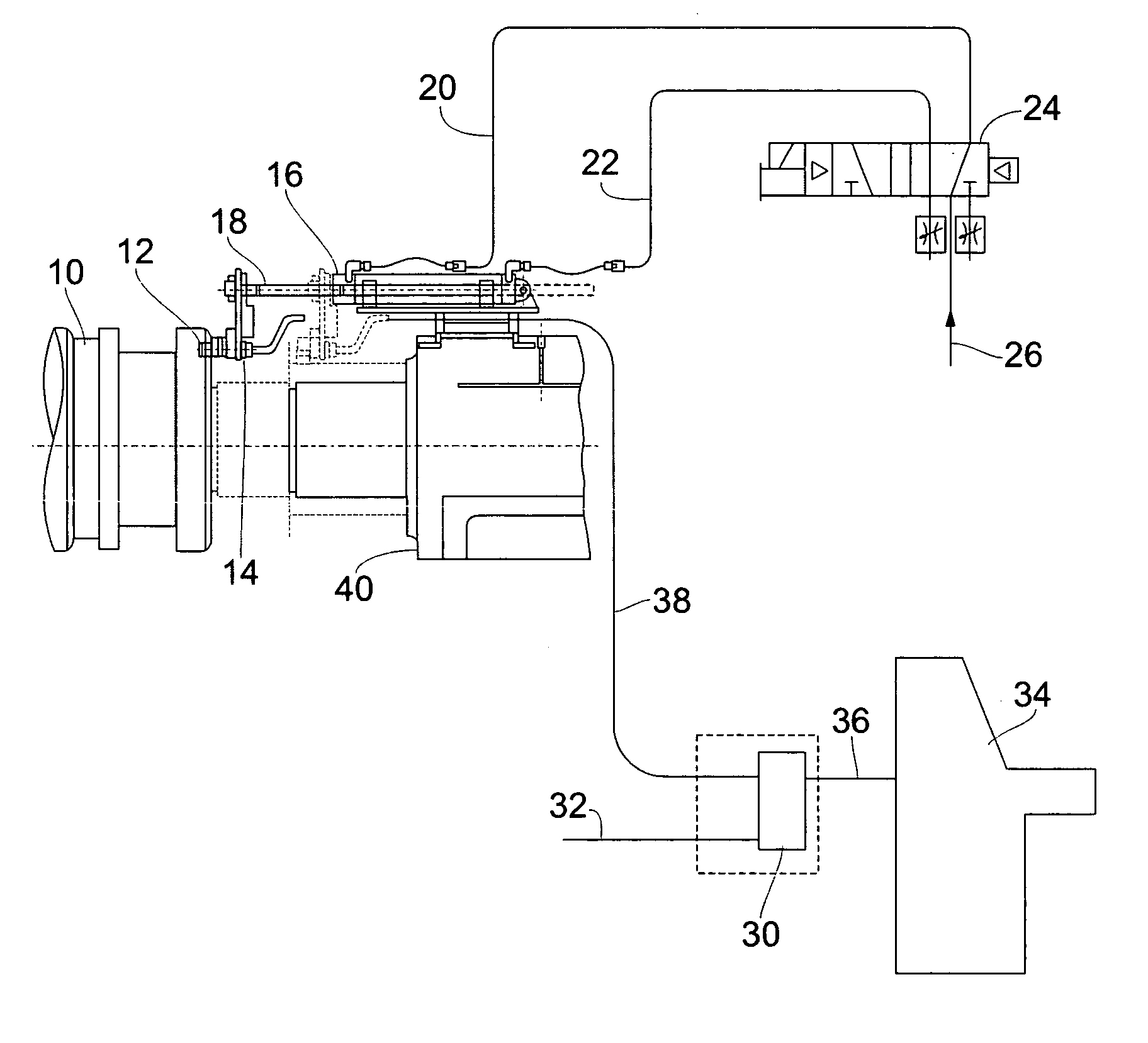
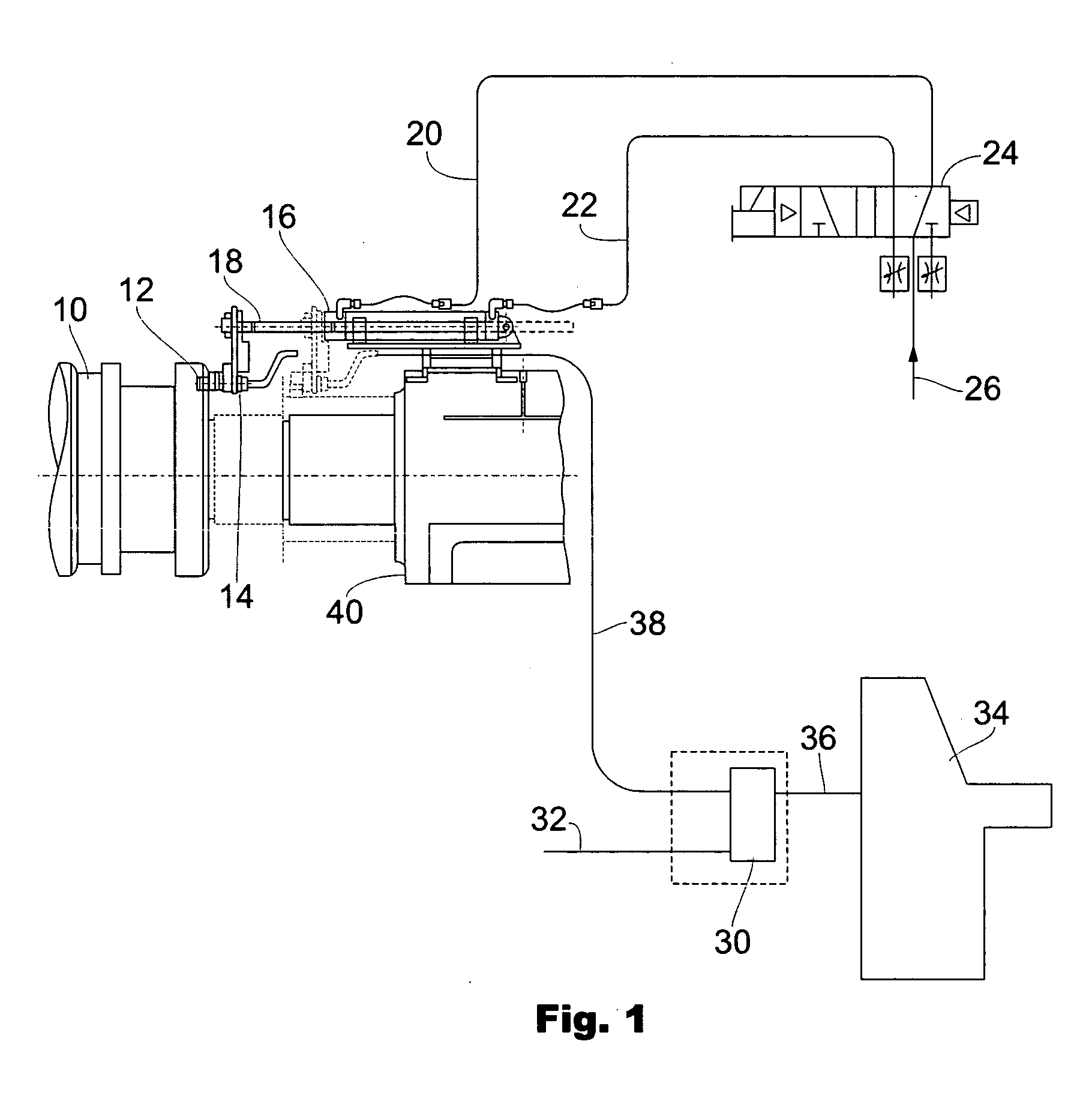
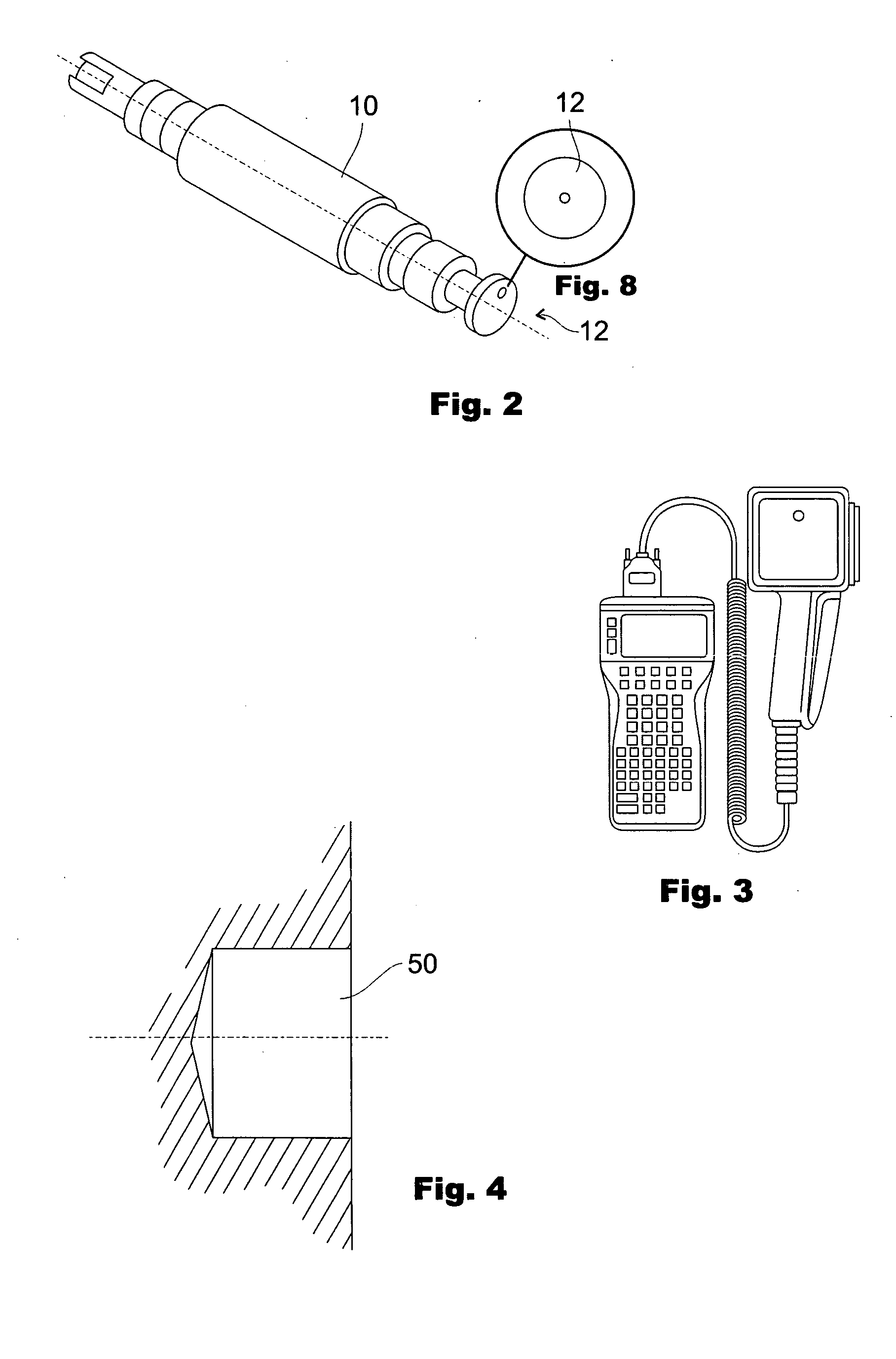
[0023] Referring to FIGS. 1 and 2, the journaled end of a work roll 10 has embedded therein an inductive read / write data carrier. The work roll is supported by a hydraulic rest (not shown). The inductive read / write data carrier is also referred to as “RFID tag”. A pneumatic cylinder 16 is mounted on the grinding machine footstock (not shown) a pre-determined distance away from the resting position of the work roll 10. The cylinder 16 contains a rod 18 axially displaceable along a pre-determined cylinder stroke. Read / write sensor 14 is connected to the end of rod 18 such that when the rod is fully extended, sensor 14 is positioned in close proximity—preferably within one inch—of the end face of roll 10.

[0024] It should be noted that RFID tag 12 embedded in the end of work roll 10 positioned at a point toward the periphery of work roll face 42. When work roll 10 is placed in position in the grinding machine, the RFID tag may fall randomly in position at any point. RFID tag 12 is not ...


PUM

PropertyMeasurementUnit
Radiusaaaaaaaaaa
Distanceaaaaaaaaaa
Electromagnetic fieldaaaaaaaaaa

Abstract

The present invention discloses a method, system and apparatus for use in a roll grinding machine. Data is read from an RFID tag automatically by providing an RF read/write sensor on a movable cylinder rod. The RF sensor is held away from the work roll area while the work roll is loaded or removed. When the work roll is placed in the position for grinding, a signal to rotate the roll is sent to the grinding machine, and also operates to advance the cylinder rod. An RFID tag embedded in the work roll and containing identification and other data related to the work roll, is read by a read/write sensor, and the data is then transferred from the sensor to a serial control interface, which converts the data and transmits the information to the grinding machine control desk and the computer control management data base. The work roll identification information is transmitted automatically to the grinding machine, eliminating errors in transposing information manually and avoiding potential injury to personnel from having to scan the RFID tag using handheld RF read/write modules.

Description

FIELD OF THE INVENTION [0001] The disclosed invention relates to a method, system and apparatus for reading data from a rolling mill roll, and more particularly, to a method, system and apparatus for acquiring data from an RFID tag attached to a roll using a movement arm to position the receiver proximate to the RFID tag. BACKGROUND OF THE INVENTION [0002] Rolling mills for rolling steel and other metals are comprised of multiple rolls for forming metal into sheets. The rolls must be machine ground periodically in order to maintain proper surface tolerances on the sheet products. When a new roll is received in a roll shop, an RFID tag is embedded in the end face of the roll. The shop clerk, upon receipt of the new roll, assigns an identification number to the roll and writes the string of data to the RFID tag using an input device. FIG. 3 shows a typical input device. [0003] The shop then maintains a database containing a running history of the surface. wear and machining of the rol...

Claims


Application Information

Patent Timeline
IPC IPC(8): B21B28/02B23Q17/20B24B5/37B24B49/00G05B19/12G05B19/418
CPCB24B49/00B24B5/37Y02P90/02
Inventor BOLZ, WILLIAM F.
Owner USX CORP
Why Eureka
Try Eureka