Cable winder apparatus

a cable winder and cable technology, applied in the direction of take-up reel/drum arrangement, telephone set construction, etc., can solve the problems of easy friction between elements, long electrical cable twisting knots, and increase in assembly time, and achieve the effect of simple cable winder structure and easy pulling out and wounding back

Inactive Publication Date: 2007-02-27
HUANG CHIN
View PDF4 Cites 14 Cited by
  • Summary
  • Abstract
  • Description
  • Claims
  • Application Information

AI Technical Summary

Benefits of technology

[0007]The present invention is to provide a cable winder apparatus with inter-engaged wheel sets between the winding tray and clamping unit. The cable can be easily pulled out and wound back with simple cable winder structure

Problems solved by technology

A long electrical cable has the problem of twist and knot.
Therefore, the cable winder provides conduction during winding operation However, the conventional cable winder has complicated structure such the assembling time increases and friction is easily induced among elements thereof.
Moreover, the cable is arranged in a closed casing, the cable is liable to rotate during winding operation.
The winding operation is difficult when the cable is jammed in the casing.
Moreover, the conventional cable winder does not have clamping structure and the exposed cable has strain thereon due to the elastic force of the spiral spring.
It is difficult to keep exposed cable with fixed length.

Method used


Image

  • Cable winder apparatus
  • Cable winder apparatus
  • Cable winder apparatus

Examples


Embodiment Construction

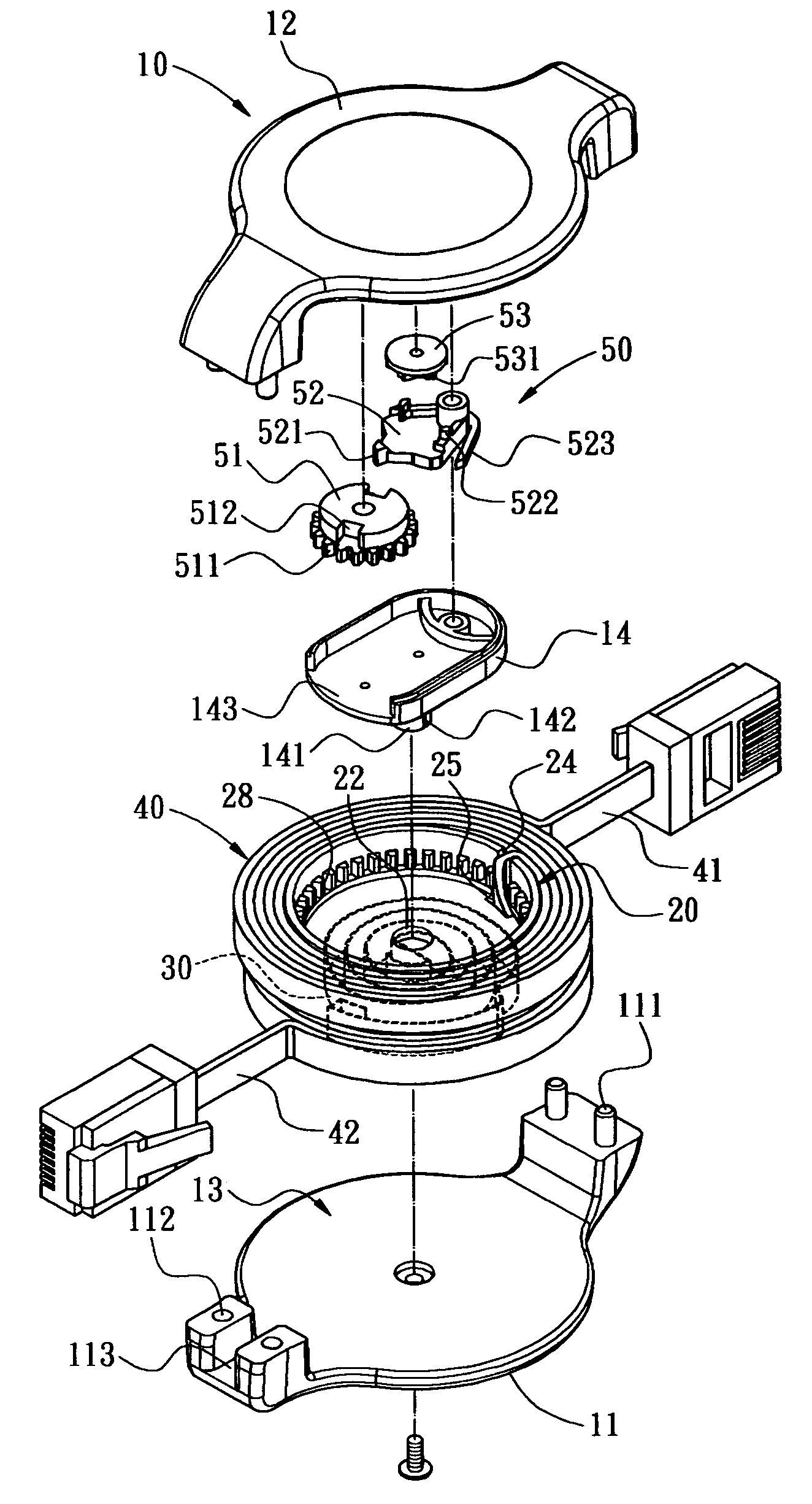
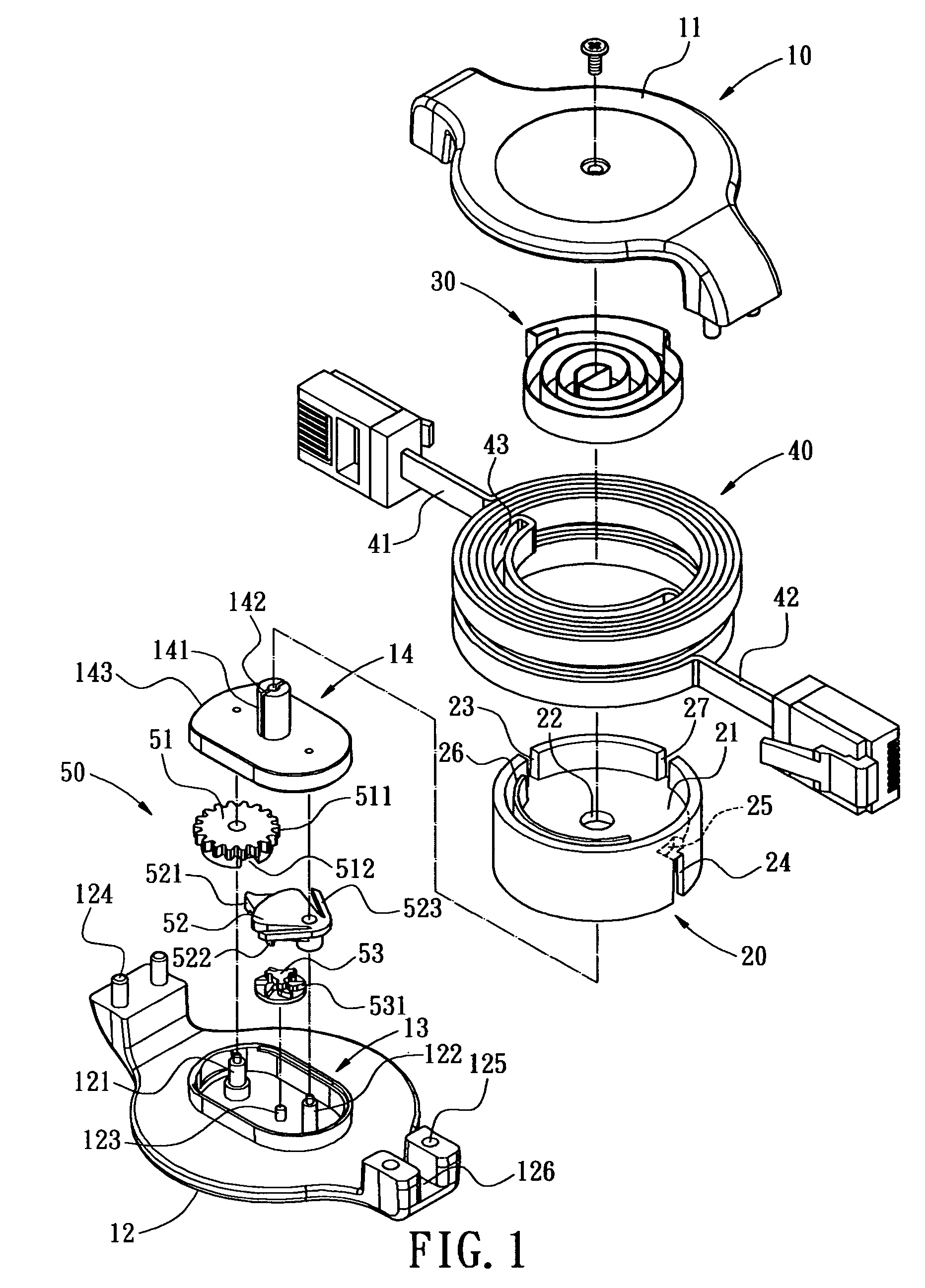
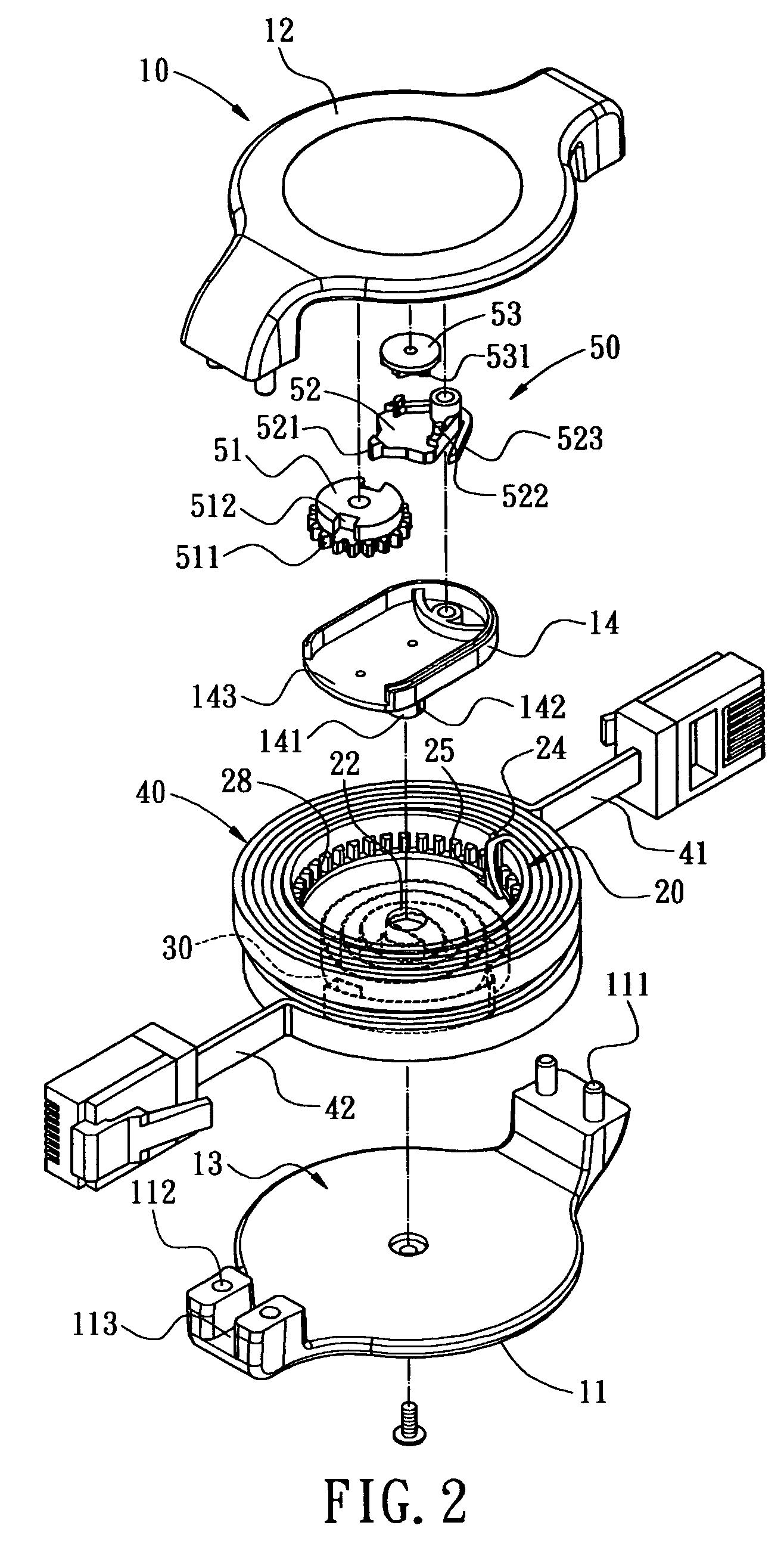
[0017]With reference to FIGS. 1 to 3, the present invention provides a cable winder apparatus comprising a casing 10, a winding tray 20, a spiral spring 30, a cable set 40 and a clamping unit 50.

[0018]The casing 10 comprises an upper shell 11 and a lower shell 12 for defining an accommodation space 13 therein. The lower shell 12 has a first post 121, a second post 122 and a third post 123 extended therefrom. A base 14 is connected to those posts 121–123 and has a shaft 141 extended at center thereof. A slit 142 is defined on the shaft 141.

[0019]An opening 143 is defined on one side of the base 14. The upper shell 11 has two first pins 111 on one side thereof and two first holes 112 defined on another sides thereof. The lower shell 12 has two second pins 124 on one side thereof and two second holes 125 defined on another sides thereof. The second pins 124 and the second holes 125 are corresponding to the first holes 112 and the first pins 111, respectively. A first cutout 113 is defi...


PUM


Abstract

A cable winder apparatus includes a casing, a winding tray, a spiral spring, a cable set, and a clamping unit. The casing has an accommodating space defined therein, a shaft in the accommodating space and two cutouts on two ends of the casing. The winding tray is pivotally connected to the shaft and has an inner wheel on one end thereof. The spiral spring is arranged in the winding tray and has one end connected to the winding tray and another end connected to the shaft. The cable set is wrapped around outer peripheral of the winding tray and composed of two stacked cables. The clamping unit is arranged in the accommodating space and has an outer wheel rotatably engaged with the inner wheel of the winding tray. The cables of the cable set can be easily pulled out and received by the cable winder apparatus.

Description

BACKGROUND OF THE INVENTION[0001]1. Field of the Invention[0002]The present invention relates to a cable winder apparatus, and more particularly to a cable winder apparatus for automatically winding function and the cable therein can be easily pulled out and wound back.[0003]2. Description of Prior Art[0004]Conventional electronic devices such as notebook computer, telephone, digital still camera or card reader are intensively employed in ordinary life or work. The electronic devices are communicated to other device by electrical cable. The electrical cable should be sufficiently long for providing practical electrical connection. A long electrical cable has the problem of twist and knot. Therefore, a cable winder is developed to receive an unused section of cable However, it still remains much room for improvement.[0005]Conventional cable winder generally comprises a casing, a winding tray, a spiral spring and a cable set. The spiral spring is retained on the winding tray and used ...

Claims


Application Information

Patent Timeline
Patent Type & Authority Patents(United States)
IPC IPC(8): B65H75/48
CPCB65H75/4434H04M1/15H02G11/02
Inventor HUANG, CHIN
Owner HUANG CHIN
Why Eureka
Try Eureka