Rectifier circuit for realizing voltage clamp of rectifier tube by using double-power transformer

A technology of power transformer and rectifier circuit, which is applied in the direction of conversion of DC power input to DC power output, output power conversion device, irreversible conversion of AC power input into DC power output, etc., which can solve the problem of rectifier junction capacitance oscillation, etc. Achieve the effect of suppressing voltage parasitic oscillation, convenient design and production, and reducing conduction loss

Active Publication Date: 2012-06-06
SHANGHAI ELECTRIC POWER ELECTRONICS
View PDF0 Cites 0 Cited by
  • Summary
  • Abstract
  • Description
  • Claims
  • Application Information

AI Technical Summary

Problems solved by technology

However, only multiple center-tapped rectifier circuits are connected in parallel, and there are still problems of leakage inductance and junction capacitance oscillation of rectifier devices

Method used


Image

  • Rectifier circuit for realizing voltage clamp of rectifier tube by using double-power transformer
  • Rectifier circuit for realizing voltage clamp of rectifier tube by using double-power transformer
  • Rectifier circuit for realizing voltage clamp of rectifier tube by using double-power transformer

Examples


Embodiment Construction

[0029] The present invention will be described in detail below in conjunction with specific embodiments with reference to the accompanying drawings.

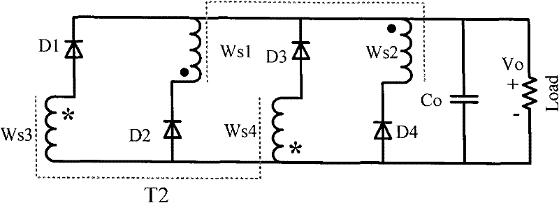
[0030] refer to Figure 4 , a rectifier circuit for rectifier tube voltage clamping with dual power transformers, including two power transformers and four rectifier diodes, the power transformers are two center-tapped rectifiers with one primary winding and two secondary windings respectively structure; in the power transformer, define the terminal with the same name of the transformer winding as the positive terminal and the other as the negative terminal, then: the cathode of the first rectifier diode D1, the negative terminal of the first secondary winding Ws1 of the first power transformer T1 terminal, the cathode of the third rectifier diode D3, and the positive terminal of the second secondary winding Ws2 of the first power transformer T1 are all connected to the positive terminal of the output filter capacitor Co; the po...


PUM


Abstract

The invention relates to the field of DC / DC conversion, and aims at providing a rectifier circuit for realizing the voltage clamp of a rectifier tube by using a double-power transformer. The rectifier circuit comprises two power transformers, four rectifier diodes, and two auxiliary capacitors, wherein two secondary windings of the power transformer have a center-tapped rectifying structure respectively. The rectifier circuit of the invention simplifies the winding structure of each transformer, and enhances the use ratio of a magnetic core window. On different occasions, primary windings of the two power transformers can adopt a serial or parallel connection structure flexibly. The rectifier circuit of the invention can effectively restrain the parasitic oscillation of voltages on the rectifier tube by aid of nondestructive capacitance energy-storage components without any active auxiliary devices; the production of the center-tapped secondary windings of the power transformer is relatively simple, and the connection between the transformers and the external electric components is reduced, which is helpful for improving power density. Therefore, the rectifier circuit is suitable for topological structures of various converters.

Description

technical field [0001] The invention belongs to the field of direct current / direct current conversion, and relates to a rectifier circuit capable of clamping rectifier tube voltage to achieve low rectifier tube voltage stress. More specifically, the present invention relates to a combined converter composed of a plurality of transformers, which adopts a rectifier circuit for secondary voltage clamping. Background technique [0002] Capacitive output center-tapped rectifier circuits (such as figure 1 ) is widely used in high-current output occasions due to its simple structure, low rectifier voltage stress, no output inductance loss, and easy realization of the soft-switching working environment of the rectifier. However, the high-frequency power transformer leakage inductance and lead inductance and the equivalent parasitic output junction capacitance of the secondary rectifier can easily generate voltage parasitic oscillations during commutation, which increases the voltag...

Claims


Application Information

Patent Timeline
Patent Type & Authority Patents(China)
IPC IPC(8): H02M7/06H02M3/335
Inventor 吴新科
Owner SHANGHAI ELECTRIC POWER ELECTRONICS
Why Eureka
Try Eureka