
Illumination unit using LED and image projecting apparatus employing the same

a technology of led light and projector, which is applied in the direction of lighting and heating equipment, television systems, instruments, etc., can solve the problems of deteriorating optical efficiency, inability to effectively project light in the range of a greater angle than usub>p, and frequent replacement of lamps for home us

Active Publication Date: 2007-02-27
SAMSUNG ELECTRONICS CO LTD
View PDF9 Cites 57 Cited by
  • Summary
  • Abstract
  • Description
  • Claims
  • Application Information

AI Technical Summary

Benefits of technology

The present invention provides an illumination unit and an image projecting apparatus that efficiently condenses light emitted from an LED module. The illumination unit includes a glass rod with a parabolic reflection surface and a concave portion at the focal point of the reflection surface. The light guide portion of the illumination unit has a rectangular section, and the surface of the light guide portion parallel to the light incident surface is stepped from the light incident surface in a direction in which the rectangular section decreases. The image projecting apparatus includes multiple illumination units emitting lights of different colors, an optical modulation element sequentially modulating the lights of different colors, and a projection lens unit magnifying and projecting the modulated lights. The illumination units have a concave portion at the focal point of the parabolic reflection surface, and each LED module is placed at the focal point of the reflection surface. The concave portion is filled with a buffer material to compensate for a difference in refractive index between the glass rod and the outside medium. The illumination unit and the image projecting apparatus provide efficient and high-quality lighting and imaging.

Problems solved by technology

Also, since the life span of these lamps are several thousands hours at the best, the lamps for home use need to be replaced frequently.
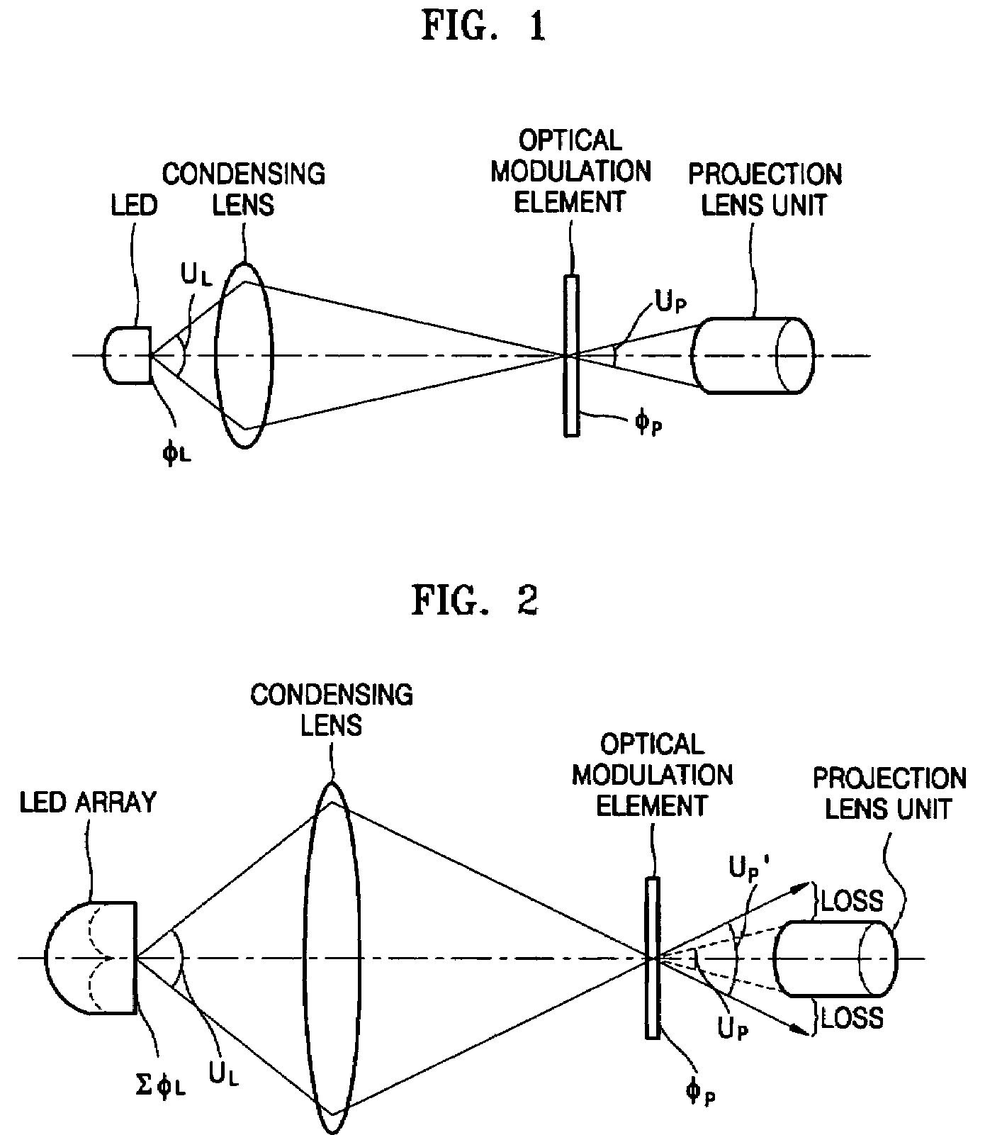
Since the angle effectively projected by a projection lens is UP, light in a range of an angle greater than UP cannot be effectively projected by the projection lens.
Thus, loss as shown in FIG. 2 is generated to deteriorate the optical efficiency.
As a result, an increase in the brightness of the image projecting apparatus is limited although the number of LED modules increases.

Method used


Image

  • Illumination unit using LED and image projecting apparatus employing the same
  • Illumination unit using LED and image projecting apparatus employing the same
  • Illumination unit using LED and image projecting apparatus employing the same

Examples


Embodiment Construction

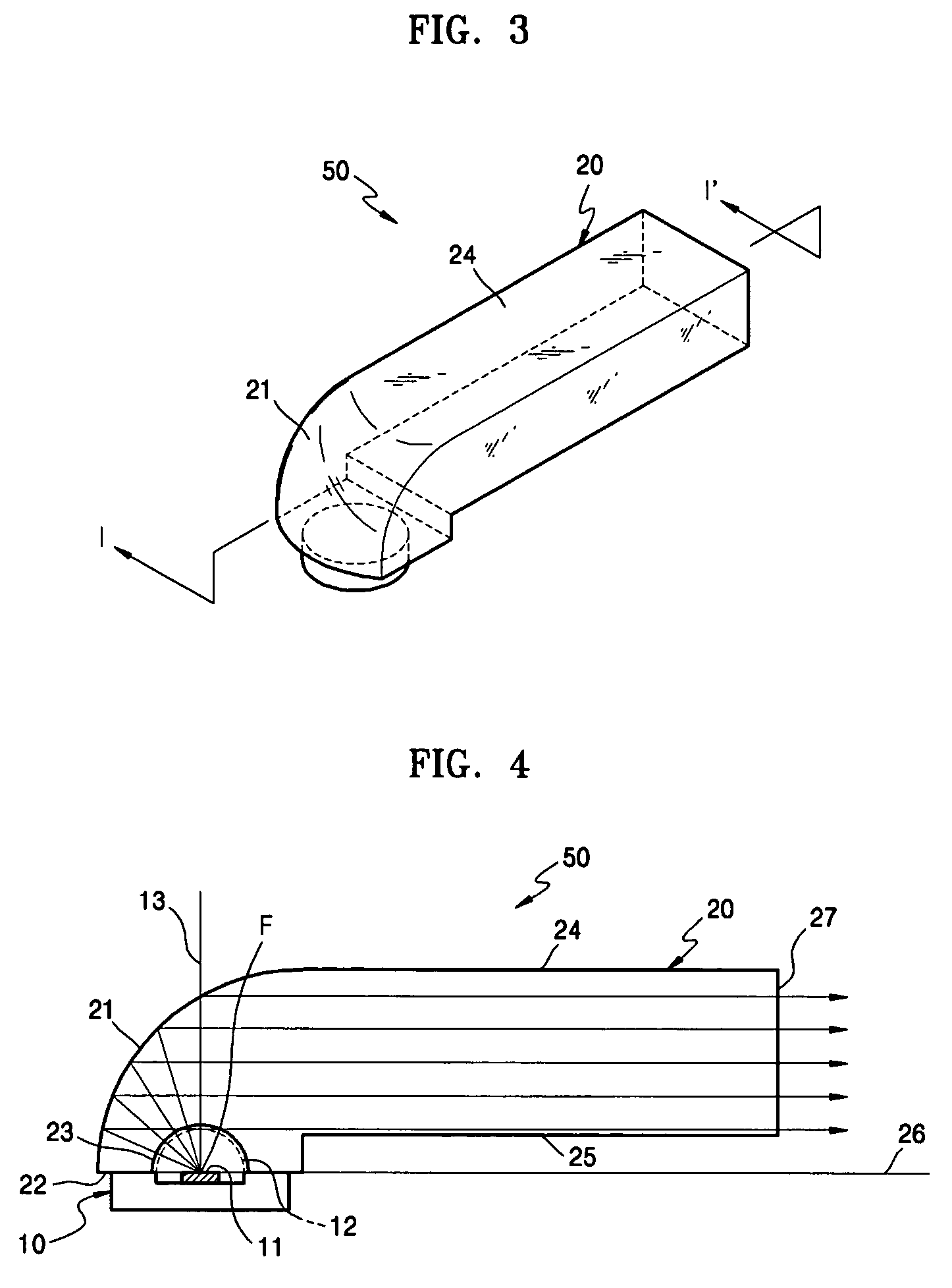
[0027]Referring to FIGS. 3 and 4, an illumination unit according to an exemplary embodiment of the present invention includes an LED module 10 and a glass rod 20. The glass rod 20 includes a parabolic reflection surface 21, a light incident surface 22, and a light guide portion 24. The light incident surface 22 faces the parabolic reflection surface 21. The light incident surface 22, for example, can be a surface which includes a principle axis 26 of the parabolic reflection surface 21, is disposed parallel to a plane including the principle axis 26, or is inclined at a predetermined angle with respect to the plane including the principle axis 26. A concave portion 23 is formed at a focal position on the light incident surface 22. The light guide portion 24 is a square pillar having a rectangular section to face the parabolic reflection surface 21 at a position different from the light incident surface 22. A surface 25 parallel to the light incident surface 22 of the light guide por...


PUM


Abstract

An illumination unit is provided which includes a glass rod including a parabolic reflection surface, a light incident surface facing the parabolic reflection surface, a concave portion formed inwardly in the light incident surface at a position of a focal point of the parabolic reflection surface, and a light guide portion facing the parabolic reflection surface and having a rectangular section. An LED module is disposed at the focal point of the parabolic reflection surface and emitting light to the parabolic reflection surface through the concave portion. A surface of the light guide portion parallel to the light incident surface is stepped from the light incident surface in a direction in which the rectangular section of the light guide portion decreases.

Description

BACKGROUND OF THE INVENTION[0001]This application claims priority from Korean Patent Application No. 10-2004-0076902, filed on Sep. 24, 2004, in the Korean Intellectual Property Office, the disclosure of which is incorporated herein in its entirety by reference.[0002]1. Field of the Invention[0003]The present invention relates to an illumination unit and an image projecting apparatus and, more particularly, to an illumination unit using a light emitting diode (LED) and an image projecting apparatus employing the same.[0004]2. Description of the Related Art[0005]In general, image projecting apparatuses include an illumination unit to illuminate an optical modulation element. A metal halide lamp or a super high pressure mercury lamp are used as a light source of the illumination unit. Since the metal halide lamp and the super high pressure mercury lamp are very large, the illumination unit becomes large accordingly. Also, since the life span of these lamps are several thousands hours ...

Claims


Application Information

Patent Timeline
Patent Type & Authority Patents(United States)
IPC IPC(8): F21V8/00
CPCF21V7/0091G02B6/4214H04N9/3114G03B21/208H04N9/3197G03B21/2013G03B21/2033H04N9/315F21Y2101/02F21Y2115/10G02B27/18H04N5/74G02B27/28G03B21/14
Inventor LEE, KYE-HOONLEE, YOUNG-CHOLLEE, WON-YONG
Owner SAMSUNG ELECTRONICS CO LTD
Learn More