Camera having a mirror box

a mirror box and camera technology, applied in the field of cameras, can solve the problems affecting the operation of the camera, etc., and achieve the effect of reducing the operation noise of the camera

Inactive Publication Date: 2007-02-27
RICOH IMAGING COMPANY
View PDF12 Cites 47 Cited by
  • Summary
  • Abstract
  • Description
  • Claims
  • Application Information

AI Technical Summary

Benefits of technology

[0008]The present invention provides a camera having a mirror box, wherein defocusing caused by deformation of a main frame of the camera to which the mirror box is fixed is prevented from occurring while the operational noise of the camera is reduced.
[0022]According to the present invention, even if an external force is applied to the camera body to a degree that the main frame is deformed or the main frame vibrates due to impact or shock given to the camera body, the mirror box is prevented from being deformed or vibrating by the shock absorbing device so that the mirror box is not deformed or vibrates. Accordingly, defocusing which may be caused by a deformation of the mirror box and image shake which may be caused by vibrations of the mirror box can be prevented from occurring, which makes high-quality imaging operation possible. In addition, mechanical vibrations which are created by operations of mechanisms installed on the mirror box during a photographic operation can be absorbed by the shock absorbing device to thereby be prevented from being transmitted to the main frame, which decreases operating noise of the camera.

Problems solved by technology

However, if a mounting screw (male screw) of a tripod which is screwed into the tripod socket 114 is tightened excessively, the external force applied to the bottom plate 112 via the tripod socket 114 becomes considerable, and accordingly occurrence of slight deformation in the main frame 110 cannot be avoided.
As a result, the front surface of the lens mount 102 tilts upwards, which in turn causes the photographing optical axis O to tilt upwards, thus causing partial defocusing of the image focused on the image pick-up device.
In addition, mechanical vibrations are created by operations of camera mechanisms installed on the mirror box assembly 120 such as an AF drive mechanism and a shutter charge mechanism during a photographic operation.
The aforementioned defocusing problem arises not only in digital cameras but also in conventional cameras using sensitive film, wherein a deformation of the main frame causes a sensitive surface of film to be deformed, thus causing defocusing; moreover, the aforementioned operational noise problem arises also in conventional cameras using sensitive film.

Method used


Image

  • Camera having a mirror box
  • Camera having a mirror box
  • Camera having a mirror box

Examples


Embodiment Construction

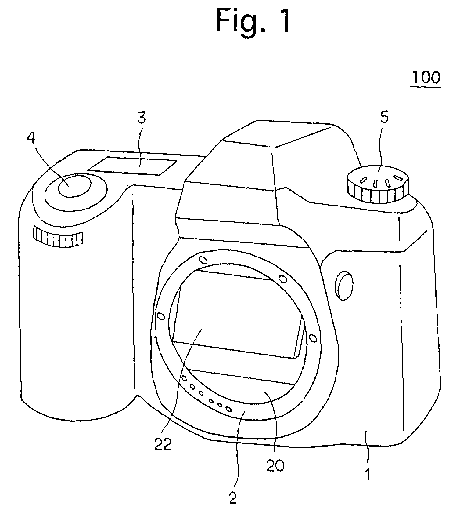
[0037]FIG. 1 is a perspective external view of an embodiment of an SLR digital camera to which the present invention is applied, viewed obliquely from the right front side of the digital camera. The digital camera 100 that is constructed as an SLR digital camera is provided on the front of a camera body 1 thereof with a lens mount (lens mount ring) 2, to which an interchangeable lens (not shown) is detachably attached. The digital camera 100 is provided on top of the camera body 1 with an LCD indicating portion 3, a release button 4 and a select dial (dial switch) 5. The camera body 1 is provided on the bottom thereof with a tripod socket (screw hole) 14 (see FIGS. 8A and 8B; not shown in FIG. 1), so that the digital camera 100 is mounted on a tripod (not shown).

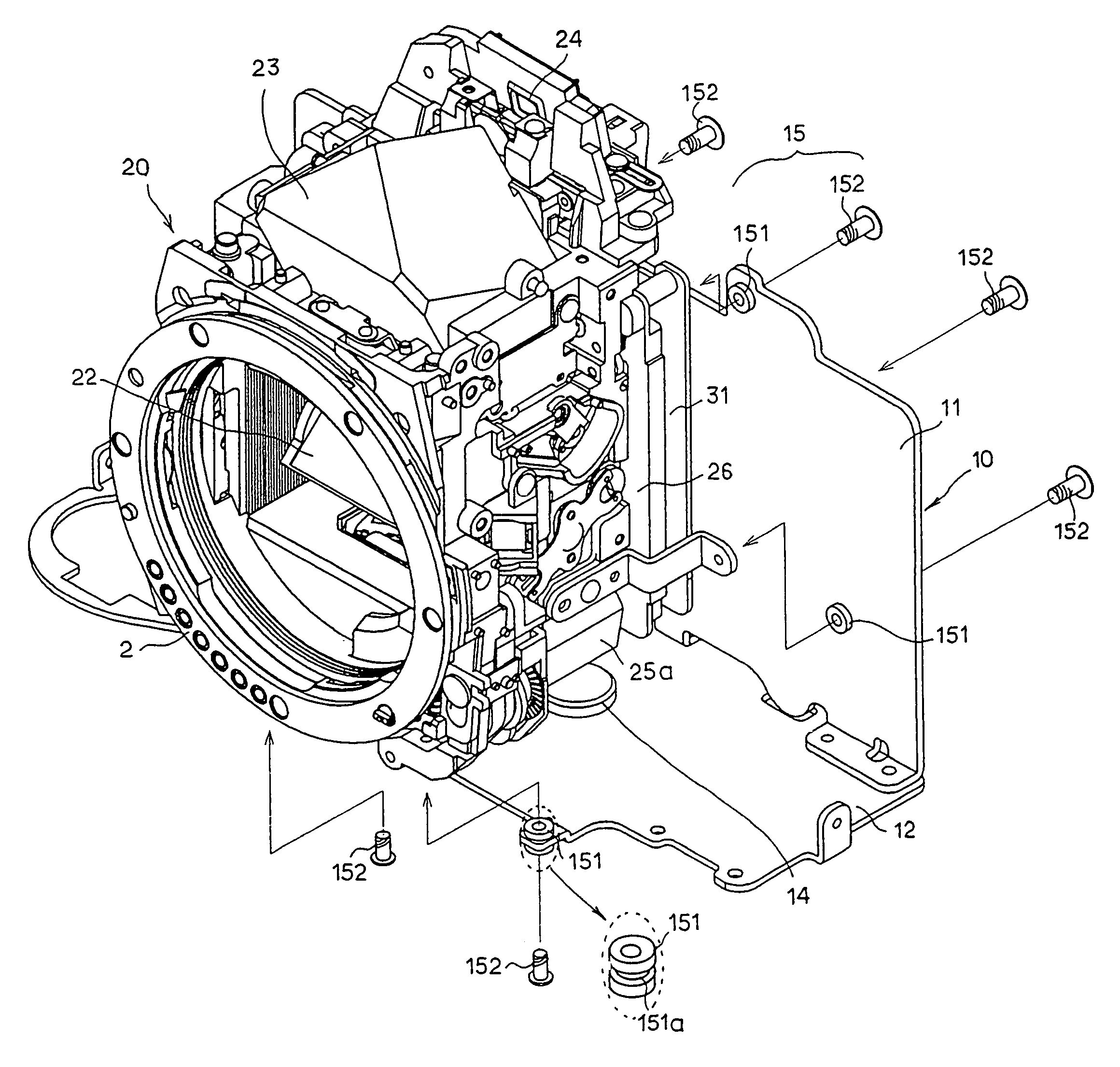
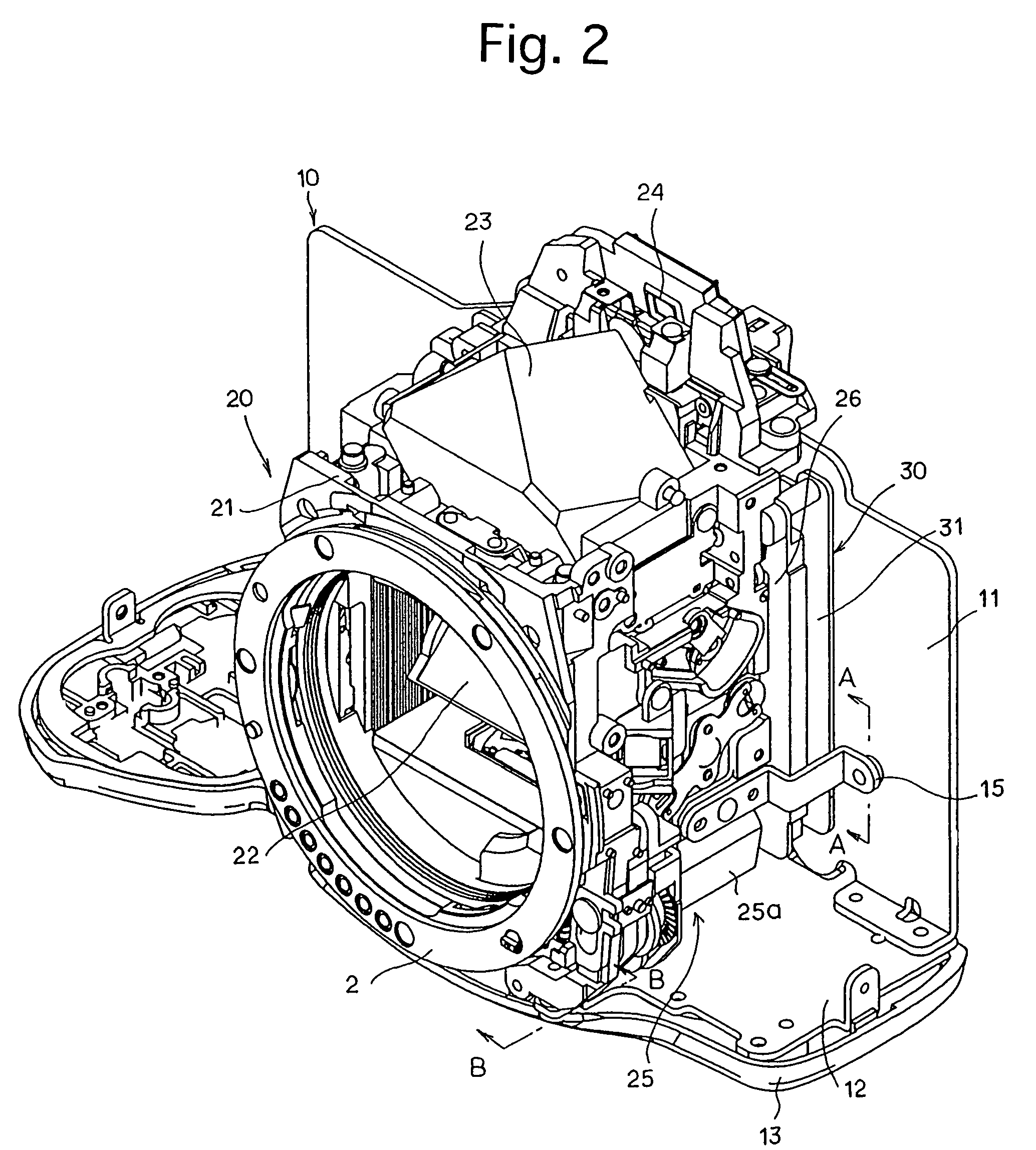
[0038]FIG. 2 is a perspective view of components of an internal structure of the digital camera 100 that include a main frame 10, a mirror box assembly 20 and a CCD unit 30, and FIG. 3 is an exploded perspective view of a po...


PUM


Abstract

A camera includes a mirror box to which a photographing lens is mounted, an object image being formed on one of an image pick-up device and sensitive film via the photographing lens; a main frame, the mirror box being provided on the main frame; and a shock absorbing device. The one of the image pick-up device and the sensitive film is supported by the mirror box, and the mirror box is supported by the main frame via the shock absorbing device.

Description

BACKGROUND OF THE INVENTION[0001]1. Field of the Invention[0002]The present invention relates to a camera including an image pick-up device such as a CCD image sensor or a photosensitive film, for photographic use, and more specifically relates to such a camera having a structure. preventing a mirror box of the camera, which supports an optical element such as a quick-return mirror, from being deformed, especially by external forces.[0003]2. Description of the Related Art[0004]In digital cameras including an image pick-up device such as a CCD image sensor or conventional cameras using photosensitive film, for photographic use, a mirror-box fixing structure wherein a main frame in a camera body is made of a material possessing a high stiffness such as a stainless steel and wherein a resin-molded or die-cast mirror box is fixed to the front of the main frame has been proposed for miniaturization and weight reduction of the camera. In the case where a digital camera adopts such a struc...

Claims


Application Information

Patent Timeline
Patent Type & Authority Patents(United States)
IPC IPC(8): G03B19/12G03B17/02H04N5/225H04N101/00
CPCG03B19/12
Inventor KUROSAWA, YUICHI
Owner RICOH IMAGING COMPANY
Why Eureka
Try Eureka