
Synchronization of cameras in camera-based touch system to enhance position determination of fast moving objects

a technology of touch system and camera, applied in the field of camera-based touch system, can solve the problems of inaccurate and unpredictable triangulation, and achieve the effect of accurately determined position of the pointer

Active Publication Date: 2007-02-27
PIXART IMAGING INC
View PDF66 Cites 130 Cited by
  • Summary
  • Abstract
  • Description
  • Claims
  • Application Information

AI Technical Summary

Benefits of technology

[0024]The present invention provides advantages in that since the position of the pointer is derived from synchronized camera image data, the pointer position relative to the touch surface can be accurately determined using triangulation. In the case of asynchronously captured images, the pointer position data derived from images is adjusted to approximate pointer position data that would have been derived from the images had the images been synchronously captured. In this manner, the position of the pointer can be accurately determined using triangulation notwithstanding the asynchronous image acquisition.

Problems solved by technology

This of course makes the results of triangulation unpredictable and inaccurate.

Method used


Image

  • Synchronization of cameras in camera-based touch system to enhance position determination of fast moving objects
  • Synchronization of cameras in camera-based touch system to enhance position determination of fast moving objects
  • Synchronization of cameras in camera-based touch system to enhance position determination of fast moving objects

Examples


Embodiment Construction

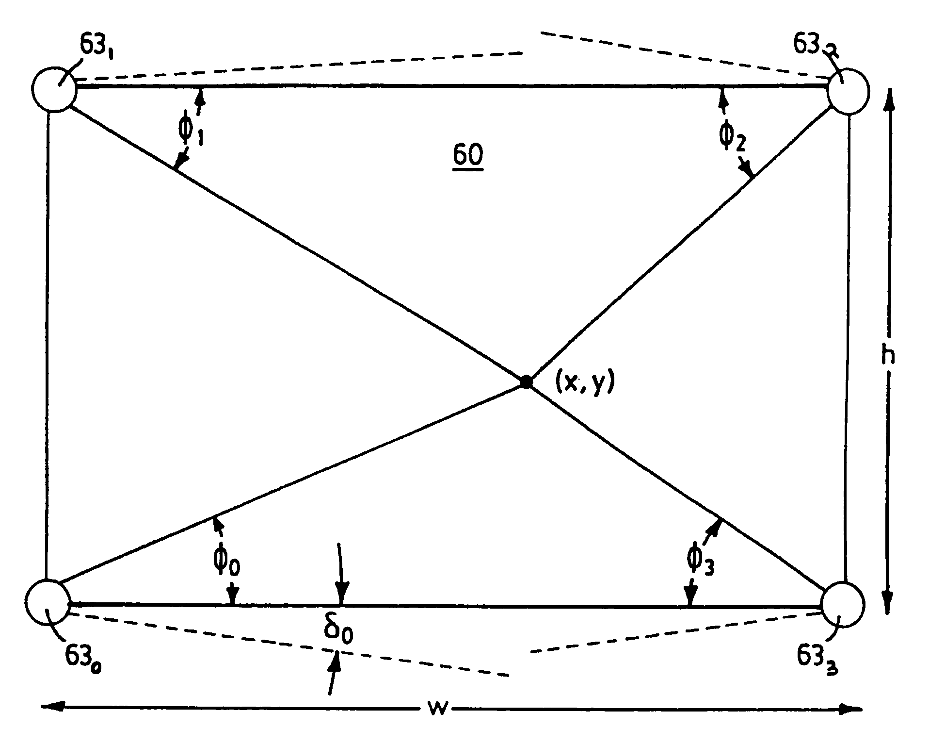
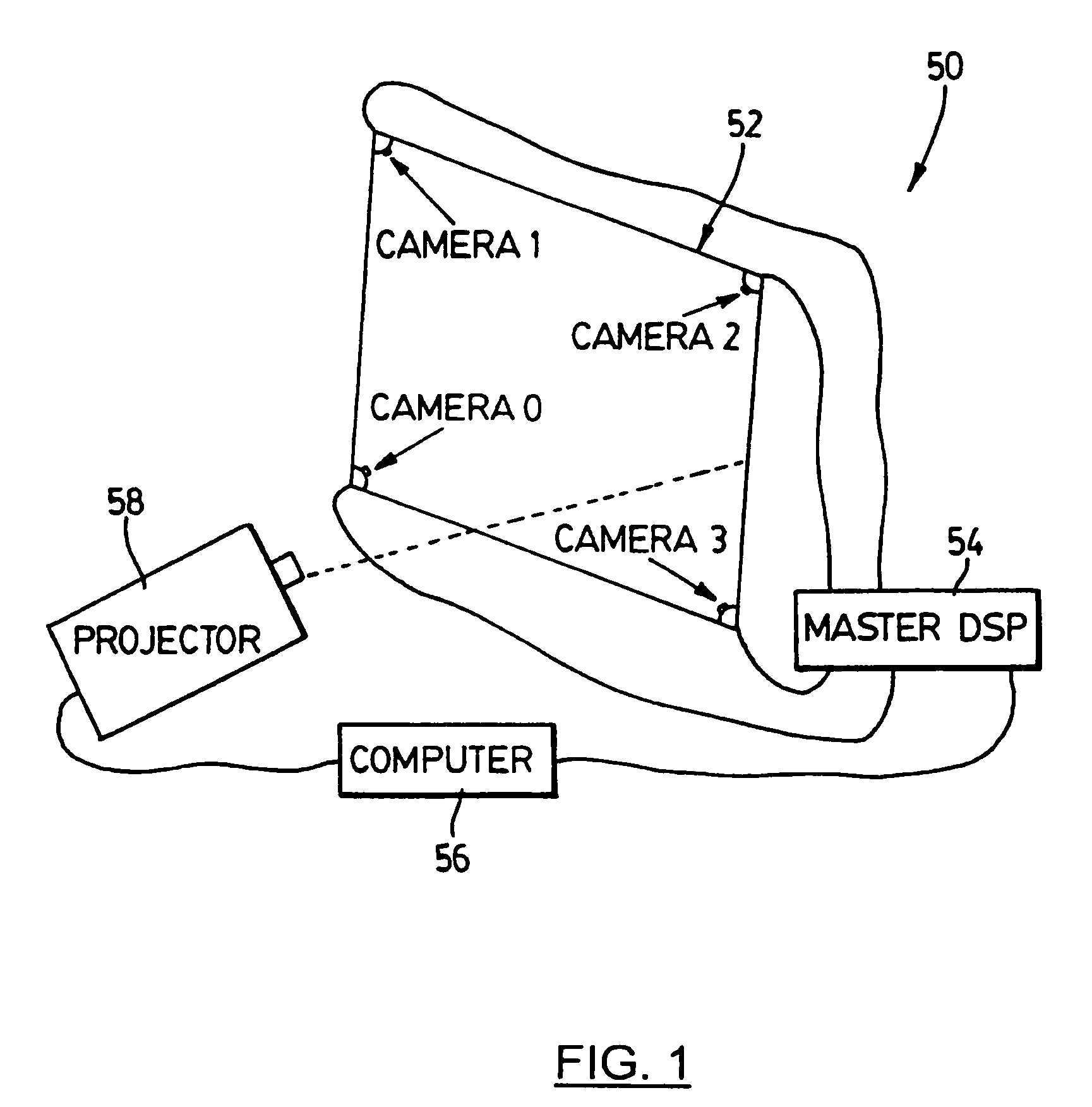
[0034]Turning now to FIG. 1, a camera-based touch system such as that described in International PCT No. WO 02 / 03316 filed on Jul. 5, 2001, assigned to the assignee of the present invention, the contents of which are incorporated herein by reference, is shown and is generally identified by reference numeral 50. As can be seen, touch system 50 includes a touch screen 52 coupled to a digital signal processor (DSP) based master controller 54. Master controller 54 is also coupled to a computer 56. Computer 56 executes one or more application programs and provides display output that is presented on the touch screen 52 via a projector 58. The touch screen 52, master controller 54, computer 56 and projector 58 form a closed-loop so that user contacts with the touch screen 52 can be recorded as writing or drawing or used to control execution of application programs executed by the computer 56.

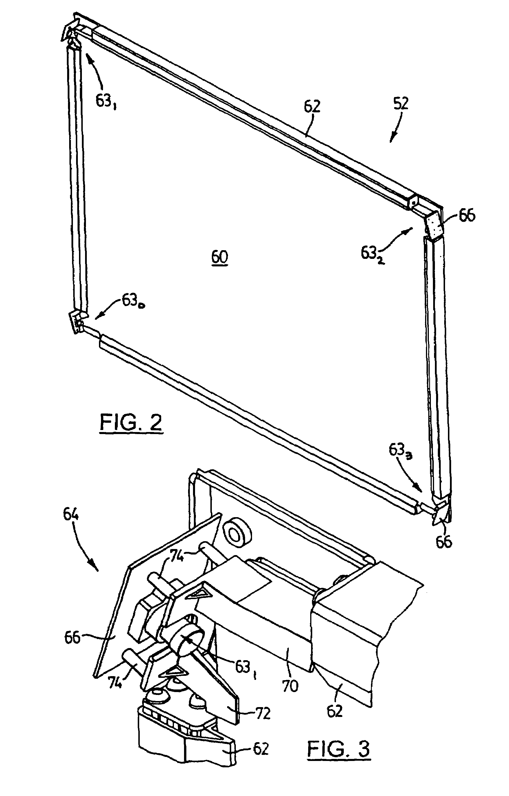
[0035]FIGS. 2 to 4 better illustrate the touch screen 52. Touch screen 52 includes a touch surface...


PUM


Abstract

A camera-based touch system includes at least one pair of cameras having overlapping fields of view and a touch surface encompassed within the overlapping fields of view across which a pointer is moved. The cameras of the at least one pair acquire images at intervals asynchronously. In order to estimate the position of the pointer relative to the touch surface from image data acquired by the at least one pair of cameras, the images are synthetically synchronized. During this process, for each camera in the pair, each acquired image is processed to determine the position of the pointer therein and the position of the pointer is recorded together with a timestamp representing the time elapsed between a reference point common to the cameras and the time the image was acquired. Successive pairs of recorded positions are interpolated to generate interpolated positions and the interpolated positions are recorded together with synchronization times representing times the images would have been acquired had the cameras been synchronized. Interpolated positions generated by the cameras having equivalent associated synchronization times are determined and these interpolated positions are triangulated to estimate the position of the pointer relative to the touch surface.

Description

[0001]This application claims the benefit of U.S. patent application Ser. No. 10 / 180,897, filed Jun. 27, 2002. The entire contents of this prior application are incorporated herein by reference.FIELD OF THE INVENTION[0002]The present invention relates generally to camera-based touch systems and in particular to synchronization of camera images in a camera-based touch system to enhance position determination of fast moving objects.BACKGROUND OF THE INVENTION[0003]Camera-based touch systems that use cameras to acquire images of a touch surface and process the image data to determine the position of a pointer relative to the touch surface are known. For example, International PCT Application No. WO 02 / 03316 to Smart Technologies Inc. et al discloses a camera-based touch system including a passive touch surface and a plurality of cameras associated with the touch surface. The cameras have overlapping fields of view encompassing the touch surface. The cameras acquire images of the touch ...

Claims


Application Information

Patent Timeline
IPC IPC(8): G09G5/00G06F3/033G06F3/042H04N5/073H04N5/232
CPCG06F3/0428H04N5/23203H04N5/0733H04N23/66
Inventor MCCHARLES, RANDYMORRISON, GERALDWORTHINGTON, STEVEAKITT, TREVOR
Owner PIXART IMAGING INC
Learn More