Refractometer with blazed bragg gratings

a refractometer and bragg grating technology, applied in the field of refractometers, can solve the problems of deterioration in resolution and measurement accuracy, difficult control, and rapid decrease of energy contained in these modes during propagation through the fibr

Inactive Publication Date: 2007-02-27
COMMISSARIAT A LENERGIE ATOMIQUE ET AUX ENERGIES ALTERNATIVES
View PDF10 Cites 11 Cited by
  • Summary
  • Abstract
  • Description
  • Claims
  • Application Information

AI Technical Summary

Problems solved by technology

The energy contained in these modes decreases rapidly during propagation through the fibre, because of the high losses at the interface between the optical cladding and the coating protecting this fibre.
With regard to evanescent-wave sensors, the following will mainly be noted:the ageing and the deterioration of the sensitive part of such sensors, for example formed by the mediating agent deposited on the optical fibre of these sensors, which necessitates frequent recalibrations thereof, the difficulty in developing methods to compensate for the degradation in the performance of these sensors, the intensity measurement on which the use of the latter is based and which is therefore sensitive to any intensity fluctuation of the associated light source and to modification in the conditions for injecting the light into the fibre, hence a deterioration in the resolution and in the accuracy of measurements, and the need for mechanically or chemically removing the cladding from the optical fibre in order to have sufficient access to the evanescent field, which is a complex operation, is difficult to control and which weakens the optical fibre.
Among the drawbacks of surface plasmon sensors, let us mention:the difficulty in forming all-fibre miniaturized systems since systems using such sensors generally employ bulky components around an architecture which is difficult to convert into an industrial system, and the need to control perfectly the profile (mainly the thickness) of the metal layer used in such sensors and the attachment of this layer.
Among the drawbacks of devices using standard Bragg gratings, there are problems similar to those presented by the evanescent wave sensors, namely:the need to chemically or mechanically attack the cladding of the optical fibre at the measuring Bragg grating,a selectivity problem, since the Bragg peak is sensitive to parameters other than the index of the external medium (for example temperature and strain), which requires the use of compensation and correction techniques employing, for example, reference sensors, the relative weakness of the final measuring head, the difficulty in producing the transducer, requiring the optical cladding to be attacked, and relatively low sensitivity.
With regard to refractometry systems using the long period Bragg gratings, the main drawbacks are as follows:great sensitivity of the long period grating resonant to parameters other than the refractive index (for example temperature and deformations), hence the need to use compensation and correction techniques, high non-linearity of the transducer sensitivity, extremely limited multiplexing capacities since a very sensitive sensor monopolizes a large spectral range, of at least 100 nm, andlarge width of the resonant band, making it difficult to determine the peak of the latter accurately.

Method used


Image

  • Refractometer with blazed bragg gratings
  • Refractometer with blazed bragg gratings
  • Refractometer with blazed bragg gratings

Examples


Embodiment Construction

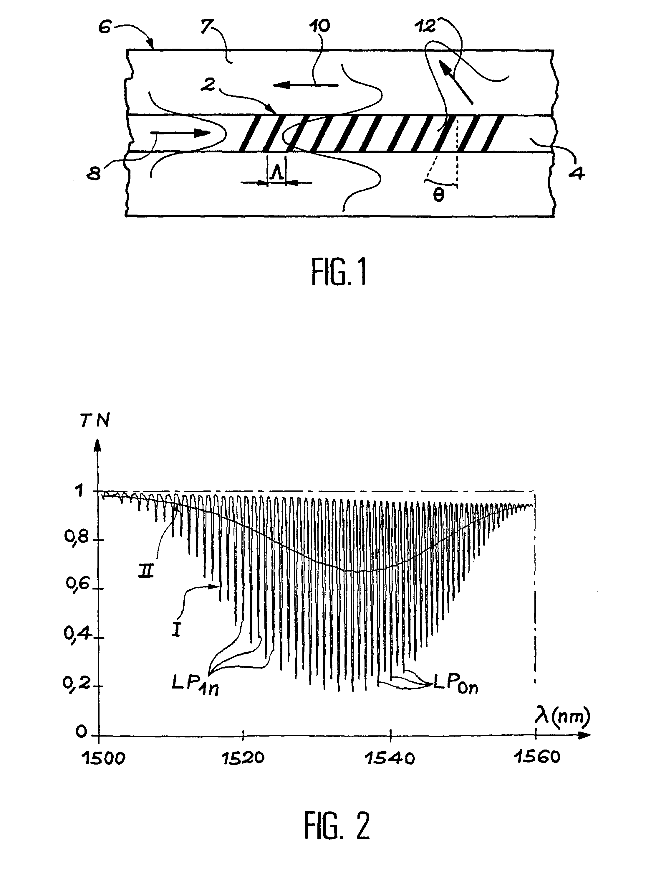
[0056]First of all, let us consider the transducers used in the present invention to measure refractive indices, that is to say blazed Bragg gratings, for example photo-inscribed in the core of optical fibres, and let us start by studying the spectral sensitivity of such a grating with any modification of the refractive index by an external medium with which the waveguide comprising this grating is in contact.

[0057]Let us therefore consider an optical fibre, or any other waveguide, in which a blazed Bragg grating has been inscribed. This grating may have been formed according to any one of the known photo-inscription methods, for example the “phase mask” or “Lloyd mirror” techniques.

[0058]In the rest of the present description, the numerical values are given only by way of illustration and are not limiting in any case. They relate to a monomode optical fibre having the following characteristics: core and cladding indices having the values of 1.462 and 1.457, respectively, at 1550 nm...


PUM

PropertyMeasurementUnit
wavelengthaaaaaaaaaa
widths at half maximumaaaaaaaaaa
width at half maximumaaaaaaaaaa

Abstract

A refractometer with blazed Bragg gratings. In order to measure the refractive index of a medium, for example a liquid or a gas, the refractometer includes a waveguide having a blazed Bragg grating, the spectral response of which depends on the refractive index of the medium and a light source in order to make this light interact with the grating. Further, spectral analysis of the light which has interacted with the grating is performed, the spectrum provided by the spectral analysis is recovered, and, from the recovered spectrum, the spectral response of the grating is correlated with one value of the refractive index of the medium.

Description

DESCRIPTION[0001]1. Technical Field[0002]The present invention relates to a refractometer, that is to say a system for measuring refractive indices.[0003]It is applicable especially to measuring the refractive index of a liquid or of a gas or of any other product or chemical compound which is contact with a waveguide, in particular deposited on this waveguide. The latter may for example be an optical fibre.[0004]The refractometer comprises one or more Bragg grating transducers formed on such a waveguide.[0005]2. Description of the Prior Art[0006]A Bragg grating, photo-inscribed in an optical fibre, is a periodic structure formed by modulating the refractive index of the core of the fibre.[0007]This structure behaves in practice like a mirror for a very narrow spectral band around a characteristic wavelength λB (wavelength for which there is phase matching between the multiple reflections within the grating) and remains transparent for all other wavelengths. This is because, since th...

Claims


Application Information

Patent Timeline
Patent Type & Authority Patents(United States)
IPC IPC(8): G01N21/41G01N21/45
CPCG01N21/45G02B6/02195G02B6/02095
Inventor LAFFONT, GUILLAUMEFERDINAND, PIERRE
Owner COMMISSARIAT A LENERGIE ATOMIQUE ET AUX ENERGIES ALTERNATIVES
Why Eureka
Try Eureka