Distributed automatic gain control system

a technology of automatic gain control and distribution, applied in power management, data switching networks, wireless communication, etc., can solve the problems of limiting the operation range of the system that combines and distributes signals, and saturating the output por

Active Publication Date: 2007-02-27
COMMSCOPE TECH LLC
View PDF4 Cites 131 Cited by
  • Summary
  • Abstract
  • Description
  • Claims
  • Application Information

AI Technical Summary

Benefits of technology

[0008]A wireless distribution system according to one aspect of the present invention includes a plurality of remote units distributed in a coverage area to receive wireless signals in the coverage area and provide the signals to a plurality of input ports to receive signals comprising the signals provided by the plurality of remote units a plurality of input power monitors operatively connected to one or more of the plurali

Problems solved by technology

The operational range of a system that combines and distributes signals within buildings or other areas where wireless signal propagation is likely to be a problem, whether the signals are digital or analog or some combination of both, is limited by the dynamic range handling capability of the system.
A large signal at a single input port may potentially saturate the output port (e.g., cause an overflow condition) if the large signal exceeds the dynamic range of the system and is not controlled in some way.
Even if a saturation level is not reached, a large signal may effectively limit the amount of traffic that the system can handle.
However, the frequency spectrum that is received, processed and distributed by the distributed communication system is shared by many services and d

Method used


Image

  • Distributed automatic gain control system
  • Distributed automatic gain control system
  • Distributed automatic gain control system

Examples


Embodiment Construction

[0009]In the following detailed description of the preferred embodiments, reference is made to the accompanying drawings that form a part hereof, and in which is shown by way of illustration specific embodiments in which the invention may be practiced. It is to be understood that other embodiments may be utilized and structural changes may be made without departing from the scope of the present invention.

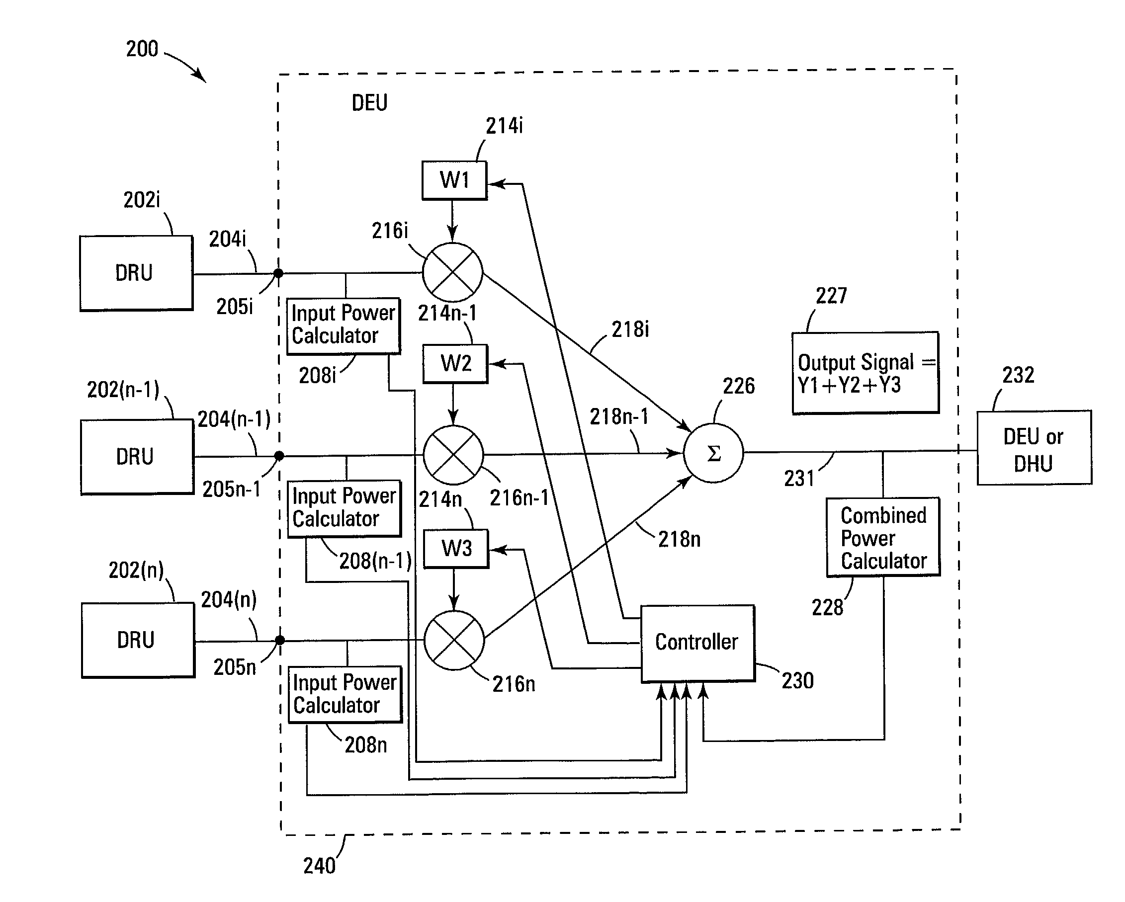
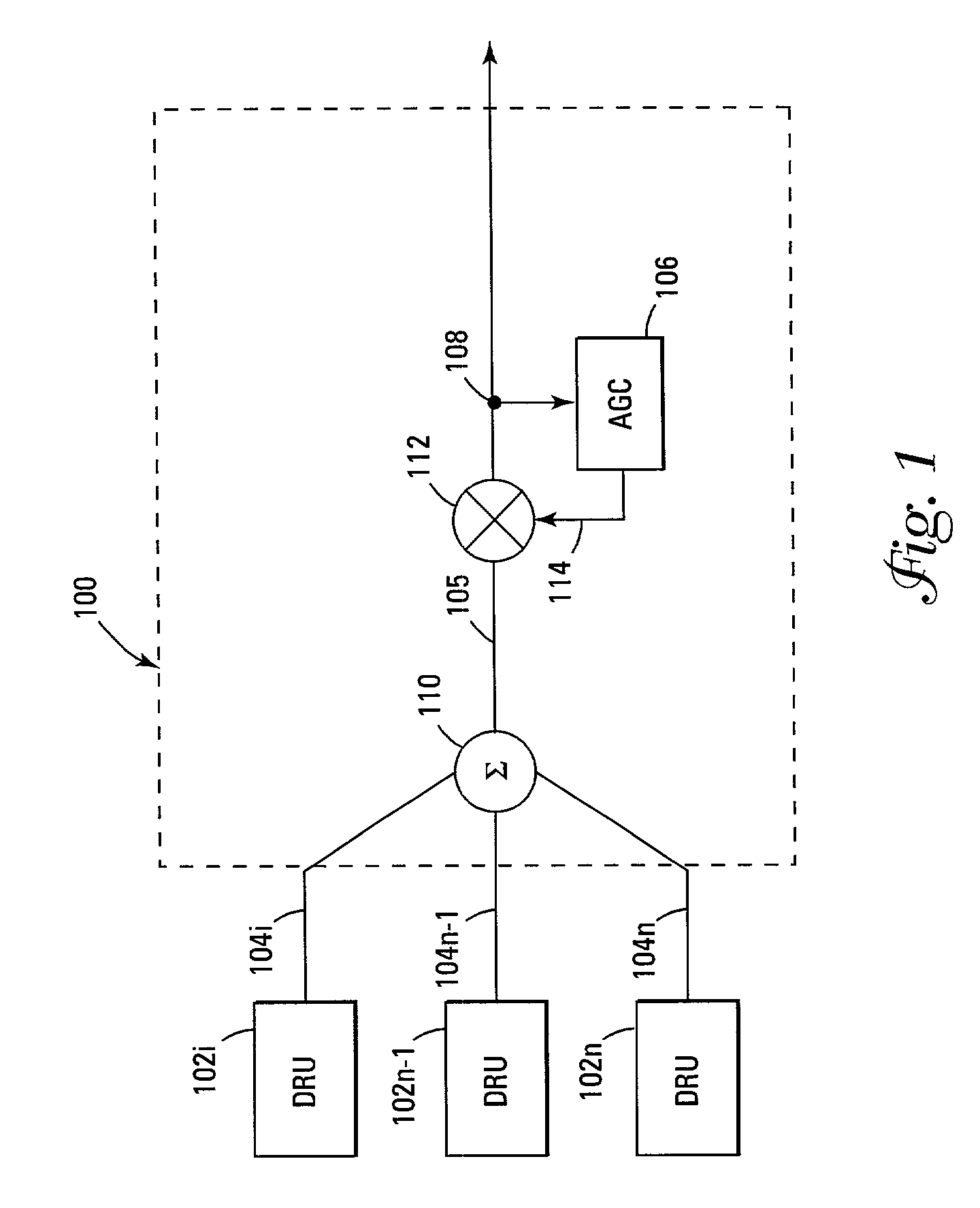
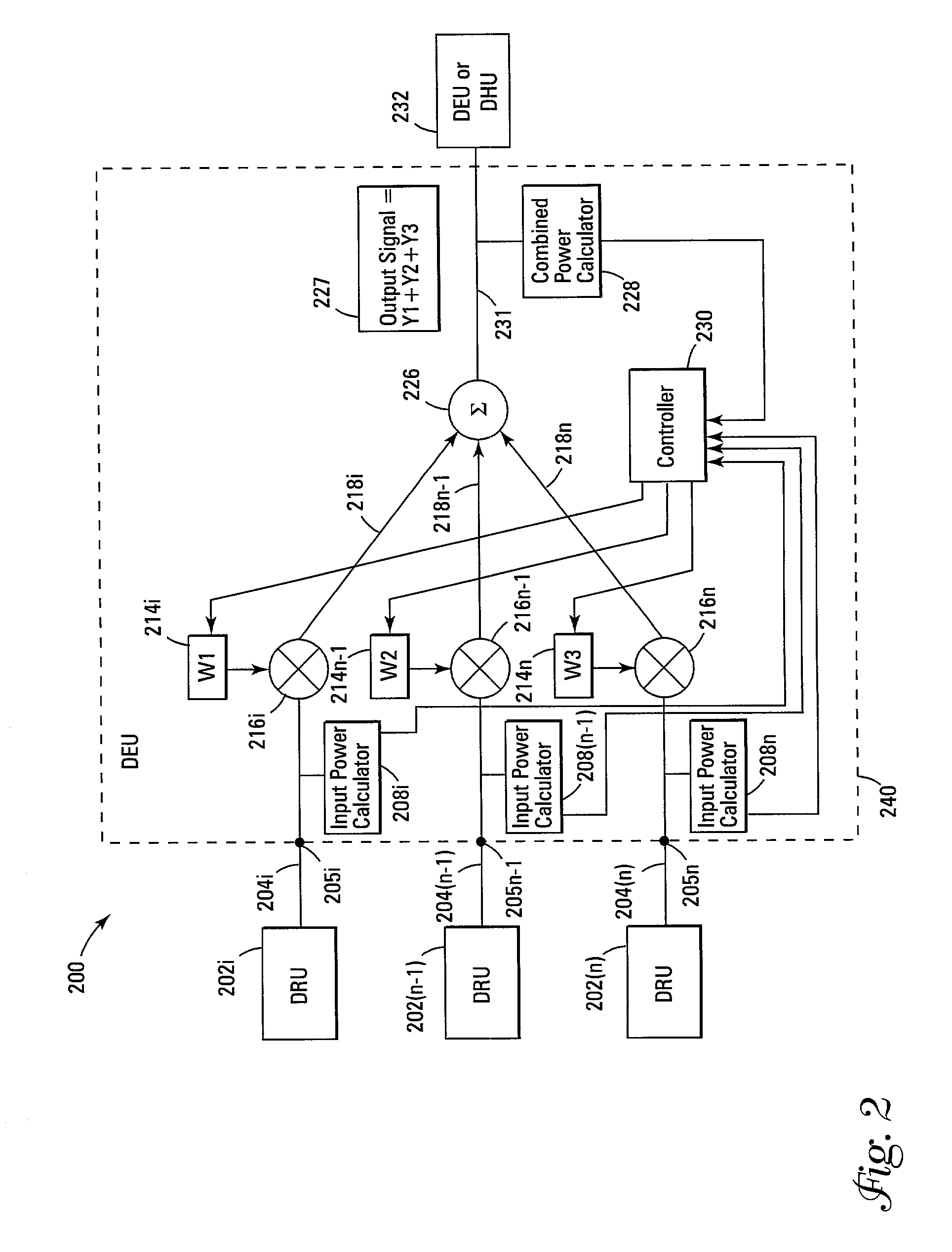
[0010]FIG. 1 is an illustration of a representative system 100 for distribution of wireless signals in a difficult environment for wireless signal propagation, such as in a large building or enclosure. The present invention is not limited to wireless signal propagation in and around buildings or other enclosures but is applicable to enhanced wireless systems for any coverage area. The system 100 includes a number of digital remote units (DRUs) 102i to 102n that receive a frequency spectrum of wireless signals such as may be transmitted by low power wireless devices in and around the...


PUM


Abstract

A wireless distribution system includes a number of remote units distributed in a coverage area to receive wireless signals and to provide the signals through the distribution system to input ports of a node where the signals are combined, a number of input power monitors operatively connected to one or more of the input ports to determine power levels of signals received at the input ports, variable gain controllers to control signals received at some or all of the input ports, a node to combine a plurality of signals from the plurality of input ports, and a controller to provide control signals to control one or more of the variable gain controllers.

Description

TECHNICAL FIELD[0001]The present invention is related to a high capacity distributed communications system, and more particularly to a distributed automatic gain control (AGC) system for use in a point-to-multipoint communication system in which wireless (radio frequency or otherwise) signals are distributed in buildings or other areas where wireless signal propagation is likely to be a problem.BACKGROUND INFORMATION[0002]The operational range of a system that combines and distributes signals within buildings or other areas where wireless signal propagation is likely to be a problem, whether the signals are digital or analog or some combination of both, is limited by the dynamic range handling capability of the system. In a distributed system, such as the one disclosed in U.S. patent application Ser. No. 09 / 619,431, “Point-To-Point Digital Radio Frequency Transport,” filed on Jul. 19, 2000, incorporated herein by reference as if fully set forth, signals of varying levels are present...

Claims


Application Information

Patent Timeline
IPC IPC(8): H04B7/00H04B1/06H03F3/21H03F3/24H04B7/005
CPCH03F3/211H03F3/24H04W52/343H04W52/346H03F2200/451H03F2203/21118H04W52/52H03F2203/21163H04W52/146H03F2203/21142
Inventor SOLUM, JEFF
Owner COMMSCOPE TECH LLC
Why Eureka
Try Eureka