Floor cleaning machine

a cleaning machine and floor technology, applied in carpet cleaners, instruments, photosensitive materials, etc., can solve the problems of insufficient width of the main squeegee, limiting the ability of the machine to clean narrow aisles,

Active Publication Date: 2007-03-06
NILFISK
View PDF23 Cites 33 Cited by
  • Summary
  • Abstract
  • Description
  • Claims
  • Application Information

AI Technical Summary

Problems solved by technology

One problem with current cleaning machines is when a machine is operated to make a turning maneuver to either avoid an obstacle, change directions or move from one aisle to another aisle.
When the machine is effecting a turning maneuver, the main squeegee may not be wide enough to squeegee the entire path of liquid at the brush assembly.
The squeegee can be made wider but the extra width limits the machine's ability to clean narrow aisles.

Method used


Image

  • Floor cleaning machine
  • Floor cleaning machine
  • Floor cleaning machine

Examples


Embodiment Construction

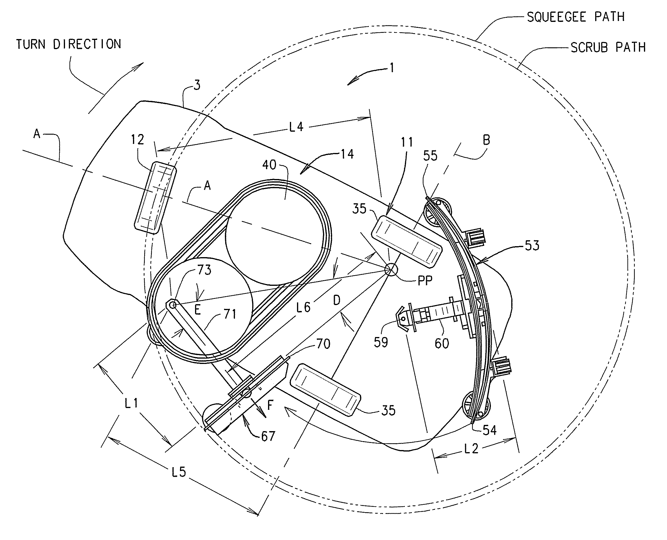
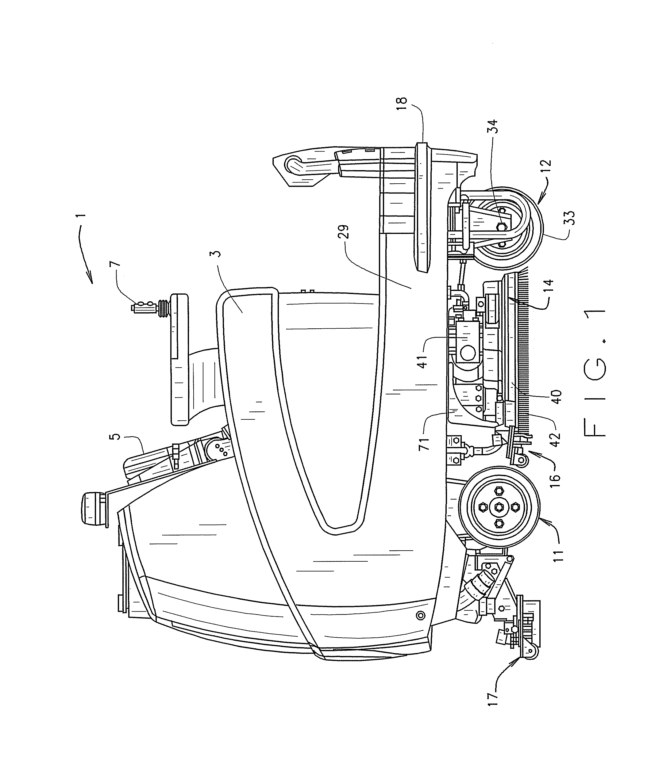
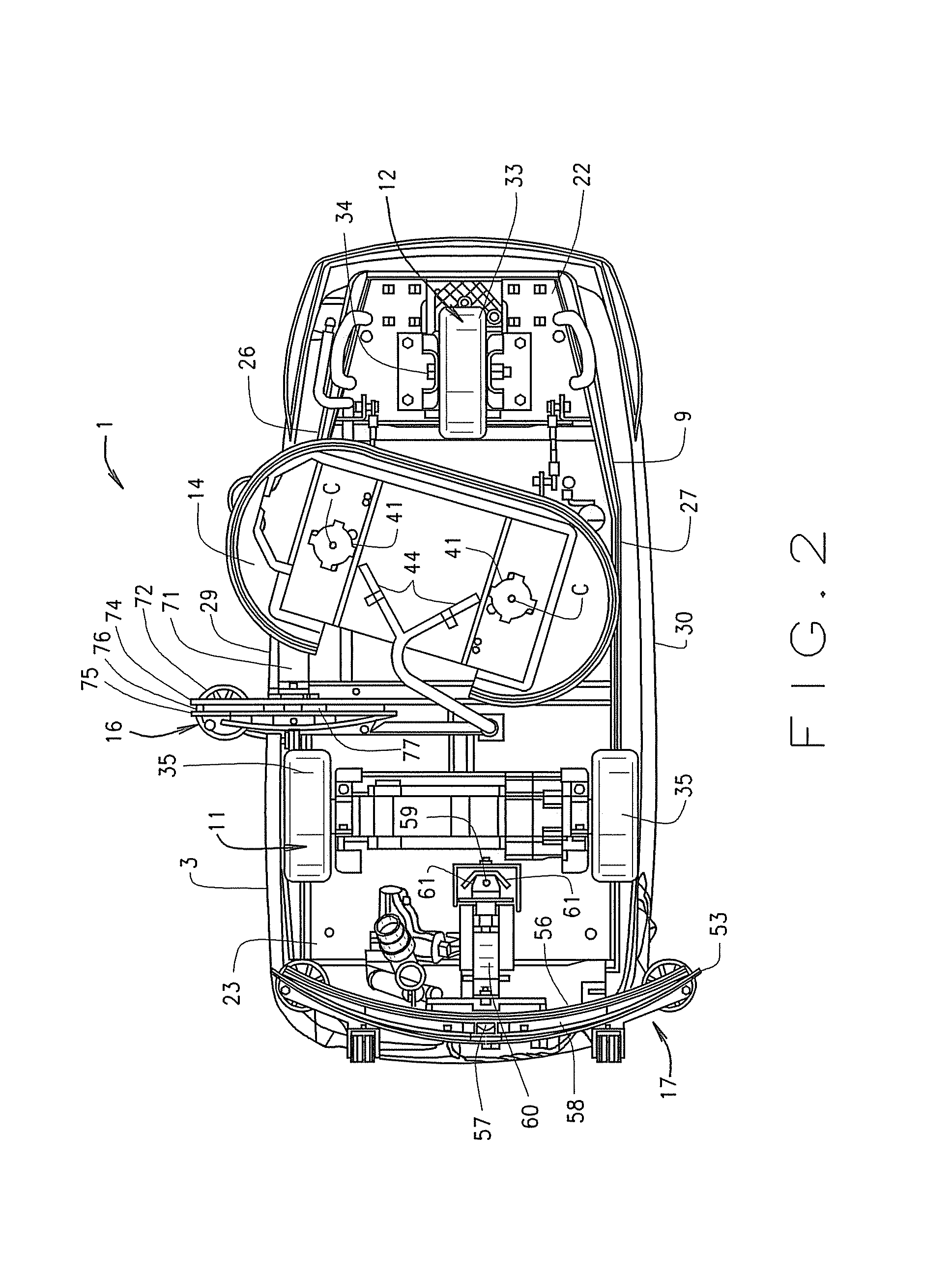
[0015]The reference numeral 1 designates generally a floor cleaning machine. In the illustrated structure, the cleaning machine 1 is of the rider type and includes a body, designated generally 3, used to enclose various machine components, for example, an engine or motor, vacuum pump, drive, steering mechanism and various other mechanisms utilized by the machine 1. A driver seat 5 is also provided. A steering implement 7 such as a joystick or steering wheel is positioned adjacent the seat 5 for use by an operator to maneuver the machine 1. The machine 1 need not be a rider type or power driven and may also be of the walk-behind push type. Machine 1 includes a chassis 9 which is used for mounting various of the mechanical components such as drive and steerable wheel assemblies 11, 12 respectively, a scrubber assembly 14 and squeegee assemblies 16, 17. Many additional mechanical components (not shown) of the machine 1 may also be mounted to or carried by the chassis The body 3, seat 5...


PUM


Abstract

A floor cleaning machine is provided with at least two movable squeegees to provide coverage of the liquid applied to the floor in a path with the squeegees extending beyond the outer perimeter sides of the liquid path both during straight ahead movement and during turning maneuvers. The squeegee assemblies are carried by a chassis. A floor scrubbing device is provided to apply liquid to the floor and to mix dirt on the floor with the applied liquid. A liquid pickup device is also provided to remove the applied liquid from the floor at a position adjacent to each of the squeegee assemblies.

Description

BACKGROUND OF INVENTION[0001]Floor cleaning machines and their components are well known in the art. See, for example, U.S. Pat. Nos. 6,557,207, 6,108,859, Re.36,565 and 5,524,320. Such machines may be constructed to walk behind or to carry an operator. In general, these machines include at least one scrubbing brush or pad which is adapted for engaging an underlying floor and to have its bristles move relative to the floor while applying a liquid such as water containing soap or other cleaning compounds to the floor. The brush works the applied liquid on the floor surface loosening the dirt and suspending or dissolving it in the liquid or to form a solids / liquid mixture / solution with the dirt. A squeegee trails the brush assembly and wipes the liquid from the floor surface leaving the floor relatively dry. Usually, a vacuum is applied to the area at the blade of the squeegee to remove the liquid and dirt being wiped by the squeegee. The liquid and dirt are then transferred to a tank...

Claims


Application Information

Patent Timeline
Patent Type & Authority Patents(United States)
IPC IPC(8): A47L11/283A47L7/00A47L11/30
CPCA47L11/4038A47L11/4044A47L11/305A47L11/4072A47L11/30A47L11/4061B60L15/2036B60L2200/40B60L2240/12B60L2240/421B60L2250/24B60L50/52Y02T10/64Y02T10/70Y02T10/72
Inventor STUCHLIK, WILLIAM R.ROWAN, LEONARD W.BUKOWSKI, WILLIAM J.
Owner NILFISK
Why Eureka
Try Eureka