Wing structure of air swirling device for internal combustion engine

a technology of internal combustion engine and swirl device, which is applied in the direction of machines/engines, combustion-air/fuel-air treatment, lighting and heating apparatus, etc., can solve the problems of reduced engine output due to reduced inlet air, fuel loss, and air resistance generated when airflow is rotated, so as to increase the speed of airflow and increase the density of air , the effect of improving combustion action and engine power

Inactive Publication Date: 2005-08-23
KIM SEI YOUNG
View PDF4 Cites 21 Cited by
  • Summary
  • Abstract
  • Description
  • Claims
  • Application Information

AI Technical Summary

Benefits of technology

[0019]An object of the present invention is to provide a wing structure of an air swirling device for an internal combustion engine, which can increase the speed of airflow per unit time and raise density of air by adding revolution force to the airflow induced into the combustion chamber, so that the combustion action and the engine power are improved.
[0020]Another object of the present invention is to provide a...

Problems solved by technology

The prior arts have a disadvantage that air resistance generated when airflow is rotated cannot be prevented completely.
However, such a device exhibits high friction so that the device provides a reduced amount of inlet air and thus is used only for a gasoline engine of the carburetor type.
However, such device has some disadvantages, such as for example, reduced output of the engine due to reduced inlet air and loss of fuel because of eddy generated at a rear surface (negative pressure zone) of the wings when the air flow is swirled.
However, the slits 12 formed in the wings 11 of the conventional swirling device of the internal combustion engine are not ideal in reducing eddy, because of being formed by cutting portions of the flat sheet type wings 11 to have a generally thin and long shape.
However, only a swirling device cannot control airflow conditions because a supercharging of the air...

Method used


Image

  • Wing structure of air swirling device for internal combustion engine
  • Wing structure of air swirling device for internal combustion engine
  • Wing structure of air swirling device for internal combustion engine

Examples


Embodiment Construction

[0035]Reference will now be made in detail to the preferred embodiments of the present invention, examples of which are illustrated in the accompanying drawings.

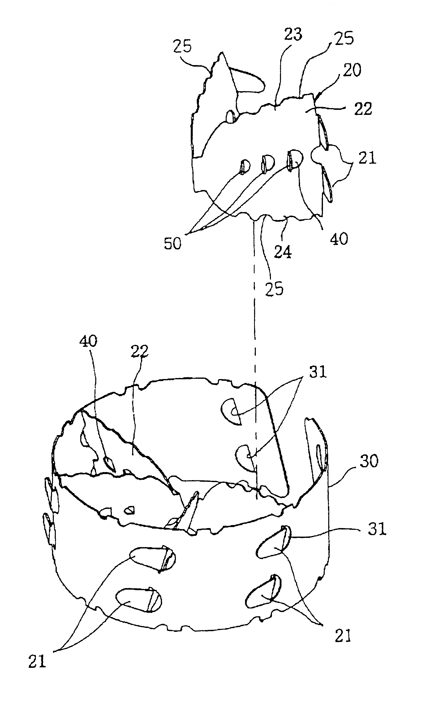
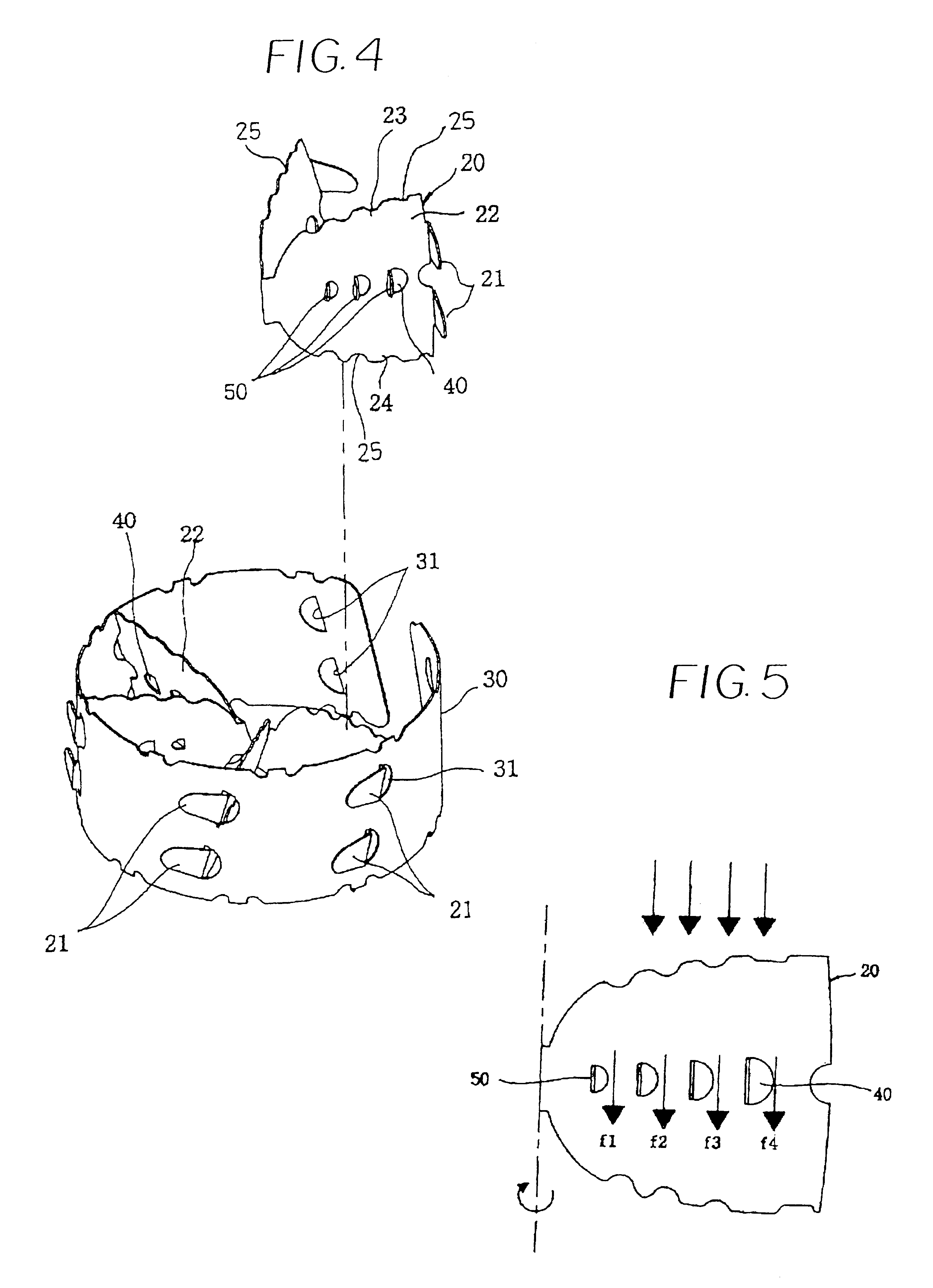
[0036]FIGS. 4 to 8 show various examples of wings of an air swirling device of an internal combustion engine according to the present invention. FIG. 4 is a perspective view of a wing structure of an air swirling device for an internal combustion engine according to a first embodiment of the present invention, and FIG. 5 is a schematic view of the auxiliary wings of the wing structure of the present invention. FIGS. 6a and 6b are views of a wing structure of an air swirling device for an internal combustion engine according to a second embodiment of the present invention, FIGS. 7a to 7c are views of examples showing various arrangements of the auxiliary wings of the wing structure of the present invention, and FIGS. 8a to 8c are views of examples showing various geometrical surface shapes of each auxiliary wing of the wing s...


PUM


Abstract

Disclosed is a wing structure of air swirling device for internal combustion engine, which has a swirling device body mounted in an air cleaner, a plurality of wings mounted slantingly and radially on the swirling device body for accelerating or increasing an airflow revolution, and one or more slits formed on prescribed positions of the plurality of wings for suppressing the formation of eddy in a negative pressure zone on the rear surface of each of the plurality of wings, includes a plurality of auxiliary wings protrudedly provided to the outside with reference to the surface of each of the wings, so that the airflow collided against the surface of each of said wings go straight ahead.

Description

[0001]This nonprovisional application claims priority under 35 U.S.C. §119(a) on patent application Ser. No. 2002-2634 filed in Korea on Jan. 28, 2002, which is herein incorporated by reference.TECHNICAL FIELD[0002]The present invention relates to a wing structure of an air swirling device for an internal combustion engine, and more particularly, to a wing structure of an air swirling device used in an air cleaner or an air duct of an internal combustion engine, which induces a swirl action of air filtered through an air cleaner of a spark ignition internal combustion engine of a carburetor or fuel injection type, a diesel engine, and so on. The wing structure of the swirling device introduces airflows into a combustion chamber of the engine, which is effective in reducing resistance due to negative pressure and eddy formed on the wings in the air swirling device, thereby improving processibility of the wings and increasing the amount of air flow and the speed of air flow in the com...

Claims


Application Information

Patent Timeline
IPC IPC(8): F02B31/00F02M29/00F02M29/06F02M35/10F02B29/00F02B31/04F02D35/00F02F1/42F02M29/02F02M35/024F23R3/14
CPCF02B31/04F02M29/06F02M35/024Y02T10/146Y02T10/12F02B67/10F02M35/10242
Inventor KIM, SEI YOUNG
Owner KIM SEI YOUNG
Why Eureka
Try Eureka