Nip and loading analysis system

a loading analysis and cross machine direction technology, applied in the direction of press section, force/torque/work measurement apparatus, instruments, etc., can solve the problems of excess nip loading damage to elastic roll covers, it is more difficult to achieve uniform loading along the entire cross machine direction length of the nip using simple crowned rolls, etc., to achieve better assessing the cross machine direction nip loading profile

Inactive Publication Date: 2007-03-06
VALMET TECH INC
View PDF34 Cites 39 Cited by
  • Summary
  • Abstract
  • Description
  • Claims
  • Application Information

AI Technical Summary

Benefits of technology

[0011]It is another feature of the present invention to provide a technique for better assessing the cross machin

Problems solved by technology

Further, as the width of papermaking machines has been increased to as much as ten meters it has become more difficult to achieve uniform loading along the entire cross mac

Method used


Image

  • Nip and loading analysis system
  • Nip and loading analysis system
  • Nip and loading analysis system

Examples


Embodiment Construction

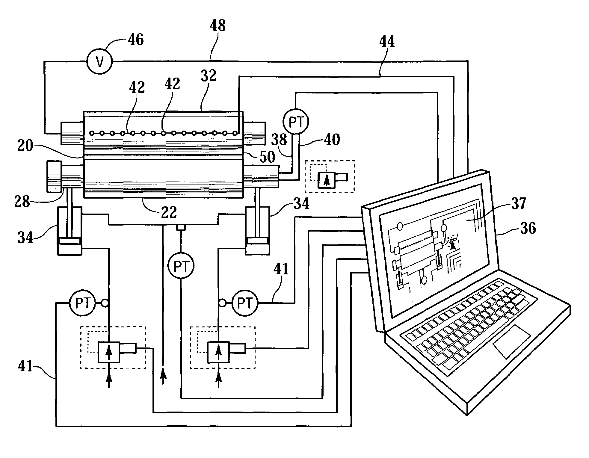
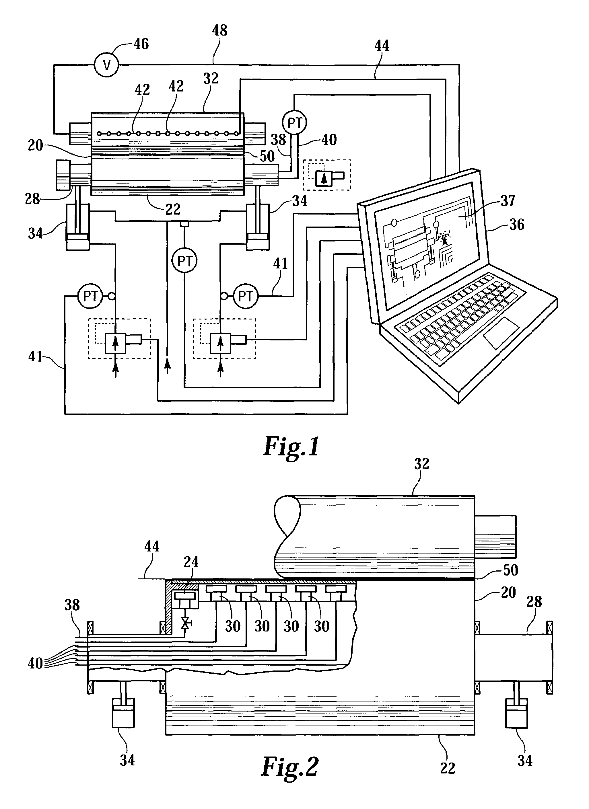
[0016]Referring more particularly to FIGS. 1–3, wherein like numbers refer to similar parts, a deflection-compensated roll 20 is shown in FIGS. 1 and 2. The deflection-compensated roll 20 has a roll shell 22 which is supported at its ends by hydraulic slide bearings 24 on a roll support beam 28. A plurality of hydraulic loading devices 30 extend between the roll shell 22 and the roll support beam 28 and are used to support the roll shell 22 so that the nip loading between the roll shell 22 and a backing roll 32, or other backing element such as a shoe, can be controlled. The roll support beam 28 is mounted to loading arms 34 represented as hydraulic pistons in FIGS. 1 and 2.

[0017]A computer 36, data acquisition devices, or other type of controller, with a display system 37 is used to monitor the loads applied by the loading arms 34 to the support beam 28 and the loads applied to the roll shell 22. The hydraulic pressure measurements PT are taken from pressure lines 38 which communic...


PUM


Abstract

A nip characterization system which has as inputs the pressure applied to the nip by the hydraulic loading devices, and loads applied at the end bearings and/or the loads applied to the roll support beam, and in addition directly measures nip load, has more than sufficient information to completely characterize the nip.

Description

CROSS REFERENCES TO RELATED APPLICATIONS[0001]Not applicable.STATEMENT AS TO RIGHTS TO INVENTIONS MADE UNDER FEDERALLY SPONSORED RESEARCH AND DEVELOPMENT[0002]Not applicable.BACKGROUND OF THE INVENTION[0003]The present invention relates to papermaking machine elements which are loaded to establish a pressure profile in general and in particular to systems for measuring the pressure profile generated by the element.[0004]In any part of a papermaking machine or paper processing machine, such as a press or calender, where a paper web is passed through a nip formed between two rolls or between a shoe and a backing roll, it is desirable to control the nip pressure in the cross machine direction, and the nip pressure profile in the machine direction. Typically it is desirable to make the nip pressure as uniform as possible in the cross machine direction so that the entire web is uniformly treated. The pressure profile in the machine direction is tailored to achieve optimal results in cale...

Claims


Application Information

Patent Timeline
IPC IPC(8): G01L5/04B30B3/02D21F3/04D21F3/06D21G1/00
CPCD21G1/002D21F3/06D21F3/04B65H2553/26B65H2553/822B65H2553/82
Inventor MUHS, BYRON G.
Owner VALMET TECH INC
Why Eureka
Try Eureka