Bicycle with optional power assist

a technology of electric assistance and bicycle, which is applied in the direction of bicycles, motorcycles, transportation and packaging, etc., can solve the problems of human power ultimately remaining the primary restriction to increase the utility of bicycles, the practical results of these performance limitations become obvious, and the human being can typically generate only 100–200 watts of power, etc., to achieve the effect of quick and easy attachment and removal

Inactive Publication Date: 2007-03-06
YOUNG GRANT E
View PDF48 Cites 28 Cited by
  • Summary
  • Abstract
  • Description
  • Claims
  • Application Information

AI Technical Summary

Benefits of technology

[0015]The present invention is a bicycle / electric-assist bicycle system that is designed to minimize engineering compromises both in the stand-alone bicycle itself and in the electric-assist system. The present invention accomplishes this by providing an optimized electric-assist system which attaches simply and quickly to an uncompromised human powered bicycle, with a non-friction wheel drive. The operator has the option of quickly attaching the electric-assist components, housed in pannier-like enclosures, to the bicycle for powerful and efficient electric assist, or the operator can use the bicycle, with all its normal efficiencies, as a stand-alone human-only powered bicycle. Importantly, even with electric-assist panniers attached, the stand-alone bicycle drive train and other systems are unaffected, making non-motored usage perfectly feasible with the exception of the added weight (which can be quickly removed when desired).

Problems solved by technology

While bicycles have evolved to be a very efficient form of human-powered transportation, human power ultimately remains the primary restriction to increased utility of the bicycle as a general transportation device.
First, human beings can typically generate only 100–200 watts of power for an extended time period (e.g., 15 minutes); the power output and length of time vary significantly from person to person.
The practical results of these performance limitations become obvious when looking at the power requirements for bicycling at higher speeds and / or traveling up grades.
Obviously, constant travel at any speed greater than 20 MPH is impossible for all but the fittest of persons.
Similarly, the same human performance limitations affect travel on grades.
Thus, regardless of the efficiency of modern bicycles, the utility of a bicycle is seriously limited by the stamina and power of the human operator and thus generally uncompetitive with motored forms of transportation in terms of speed and traveling distance.
However, designing a practical electric propulsion system for a bicycle has proven to be a formidable task as evidenced by the absence of such electric powered vehicles currently available.
The majority of these inventions use simple but inefficient friction drives to provide power to one wheel of the bicycle.
Additionally these inventions do not typically support quick removal of the propulsion system.
Such devices are not easily and conveniently removed from the bicycle, place the weight of the unit too high on the bicycle, and do not adapt to full-suspension bicycles.
However, both of these inventions rely on an inefficient friction drive wheel contacting the rear wheel of the bicycle, result in a relatively high center of gravity due to the location of weight on the bicycle frame, fail to make provisions for operation with a rear suspension bicycle, and do not provide additional storage.
Further, each inconveniently requires manual disengagement of the drive wheel in order to reduce motor drag when power assist is not required.

Method used


Image

  • Bicycle with optional power assist
  • Bicycle with optional power assist
  • Bicycle with optional power assist

Examples


first embodiment

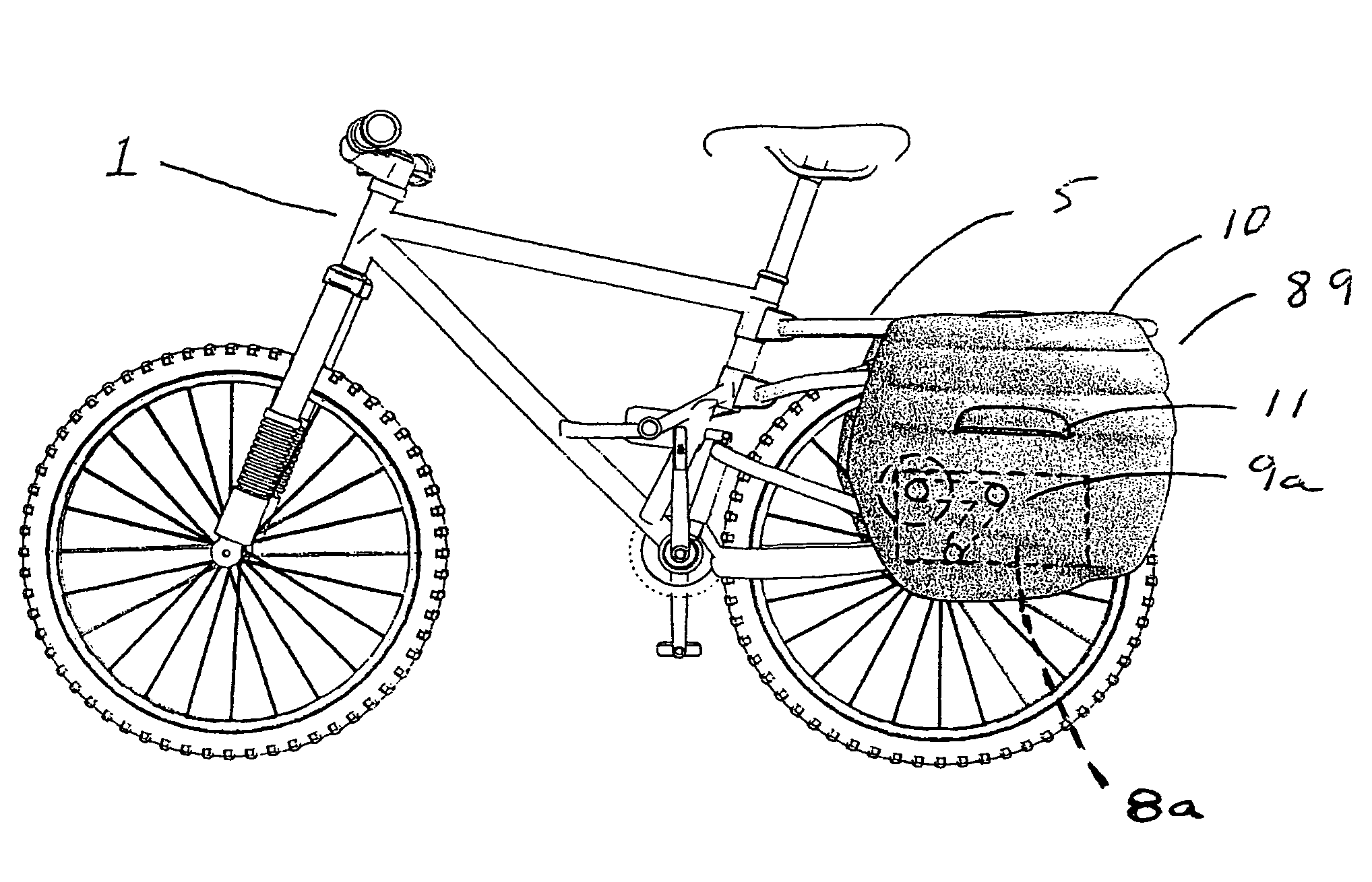
[0052]FIG. 5 shows the invention in which the hub of the rear wheel is driven directly by the motor drive unit 16 and motor 17 (schematically indicated as a circle) located in the pannier. A vertical structural connection indicated at 9b merely represents the pannier 9 as attaching the motor 17 to the rear utility rack, represented as 5a. This figure is for illustrative purposes only as motor and motor drive unit would be enclosed in the pannier with the motor mounted solidly to the pannier with clearance for the drive unit 16 to articulate with the suspension. While not the only means to transfer power from the motor to the rear axle, the motor drive unit 16 in this embodiment consists of two chains or belts 16a, 16b that share an axle at the center connection point 16c but are connected to independent cogs or sprockets (16d visible adjacent bicycle hub) at the end of each extension arm 16e, 16f of the drive unit. This power transfer mechanism provides ample freedom of motion even ...

second embodiment

[0057]FIG. 8 shows schematically one potential configuration of the invention in which a pannier based motor 32 connected to a motor drive unit 33 transmits power via a retaining mechanism 34 clasped to a large “ring” gear 35 attached to the rear wheel rim. The motor 32 is represented as a circle, and a connection of the motor to the utility rack of the bike is represented by a vertical post 9b (as in FIG. 5). The motor drive unit 33 is articulated on two parallel axes, one at the motor, not seen, and another 33a at the junction of two articulated arms 33b and 33c, each with a drive chain as indicated.

[0058]FIG. 9 shows a close-up view of the ring gear and retaining mechanism in one preferred configuration for this second embodiment of the invention. Specifically, the retaining mechanism 34 has an arm 36, bearing-mounted on a rotational shaft 38, to ensure proper alignment between the drive unit's drive gear 37 and the rim-based wheel gear or ring gear 35. The arm is spring tensione...

third embodiment

[0061]FIG. 11 is a perspective view of one possible specific configuration of the third embodiment in which a sealed straight-cut gear-to-gear final drive 44 couples to the motor drive unit 42. The bicycle's final drive 44 has a sealed housing 45. No brake disk is shown in this view.


PUM


Abstract

A bicycle is fitted with rear panniers that provide electric motor assist and a power supply for the bicycle when desired. In a preferred embodiment the bicycle has a power coupling permanently attached at the rear wheel, for receiving an output drive shaft or power coupling from the motor pannier when that pannier is installed. The drive coupling may have gear reduction. To accommodate relative up and down motion between the pannier-supporting rack and the rear tire in a rear suspension bicycle, the motor drive unit in the motor pannier articulates, or the final drive unit on the bicycle can articulate, but this is more difficult because the rear suspension motion can be complex. Both panniers are secured by a quick connect device, for both mechanical attachment and electrical connection. The bicycle functions as a normal unpowered bike when the panniers are removed.

Description

[0001]This application claims benefit of provisional application No. 60 / 488,656, filed Jul. 21, 2003.BACKGROUND OF THE INVENTION[0002]The bicycle is currently one of the most efficient means of human powered transportation in terms of converting human power into distance traveled. Modern bicycles require approximately 150 watts (0.2 HP) for consistent travel of approximately 15 MPH on level ground and less than 30 watts (0.04 HP) for travel at 5 MPH. This efficiency has been slowly improving throughout the history of the bicycle through engineering refinement; for example gearing, weight reduction, ergonomic / biometric alterations, and reduced mechanical and tire friction.[0003]This invention relates generally to the field of bicycles and electric-assist powered bicycle. Bicycles being a very efficient form of human-powered two-wheeled transportation, and electric-assist bicycles being bicycles with supplemental force to accommodate the limitations of stamina and power inherent in a ...

Claims


Application Information

Patent Timeline
Patent Type & Authority Patents(United States)
IPC IPC(8): B62M23/02B62M6/60B62M6/85B62M6/90B62M7/12
CPCB62M6/60B62M7/12B62M6/90B60L2200/12B60L50/20
Inventor YOUNG, GRANT E.
Owner YOUNG GRANT E
Why Eureka
Try Eureka