
Vehicle seat suspension and method

a technology for suspension and vehicle seats, applied in the field of vehicle seat suspension, can solve the problems of limiting the design of energy and vertical adjustment components, requiring additional space within the suspension envelope, and requiring unnecessary redundancy at increased cost, and achieve the effect of low friction construction

Inactive Publication Date: 2007-03-06
MILSCO LLC
View PDF63 Cites 74 Cited by
  • Summary
  • Abstract
  • Description
  • Claims
  • Application Information

AI Technical Summary

Benefits of technology

"The present invention is a suspension arrangement for a seat, specifically a vehicle seat, that is designed to provide a comfortable and adjustable ride. The suspension arrangement includes a seat base and a seat platform that can be adjusted in height and weight. The suspension arrangement includes a suspension arm and a biasing element that work together to oppose suspension collapse. The suspension arm is pivotally carried by a suspension housing that is releasably attached to either the platform or the base. The suspension arm arrangement can be a scissors linkage arrangement or a bell crank subassembly that allows for adjustment of suspension height and weight. The adjust assembly includes a handle that is linked to an adjuster rod that communicates with the suspension arm arrangement. The suspension housing is designed to carry the components of the suspension arrangement and includes a slot and guide notches for easy assembly. The technical effects of the invention include improved comfort, adjustable suspension, and improved performance of off-road vehicles."

Problems solved by technology

This means of assembly limits the design of the energy and vertical adjust components to that of elements that can be installed and assembled as loose members to the seat suspension in the restricted space available between the seat platform and base.
This constraint may require additional space within the suspension envelope.
The traditional embodiment may require additional components that provide unnecessary redundancy at increased cost to attach the vertical adjust and energy adjust components.
In order for an operator or seat occupant to change their static vertical position they also need to either increase or decrease the spring tension adjustment, which typically requires a significant expenditure of work or energy.
Thus, two adjustments disadvantageously must be made to change the operator's vertical position.
This is an undesirable behavior for effective vibration isolation.
Another shortcoming of conventional compact bell crank suspensions is compromised vibration isolation.
The compact size limits the optimization of the bell crank leverage ratio, which results in higher spring rates, higher joint loads, and therefore more system friction.
What is still further needed is a seat suspension of compact construction that results in a shorter collapse height.

Method used


Image

  • Vehicle seat suspension and method
  • Vehicle seat suspension and method
  • Vehicle seat suspension and method

Examples


Embodiment Construction

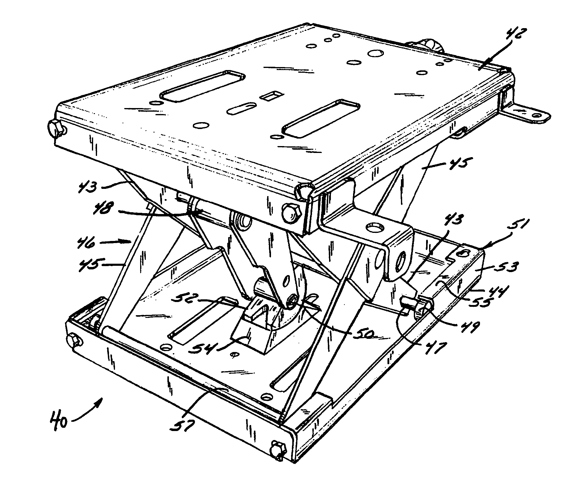
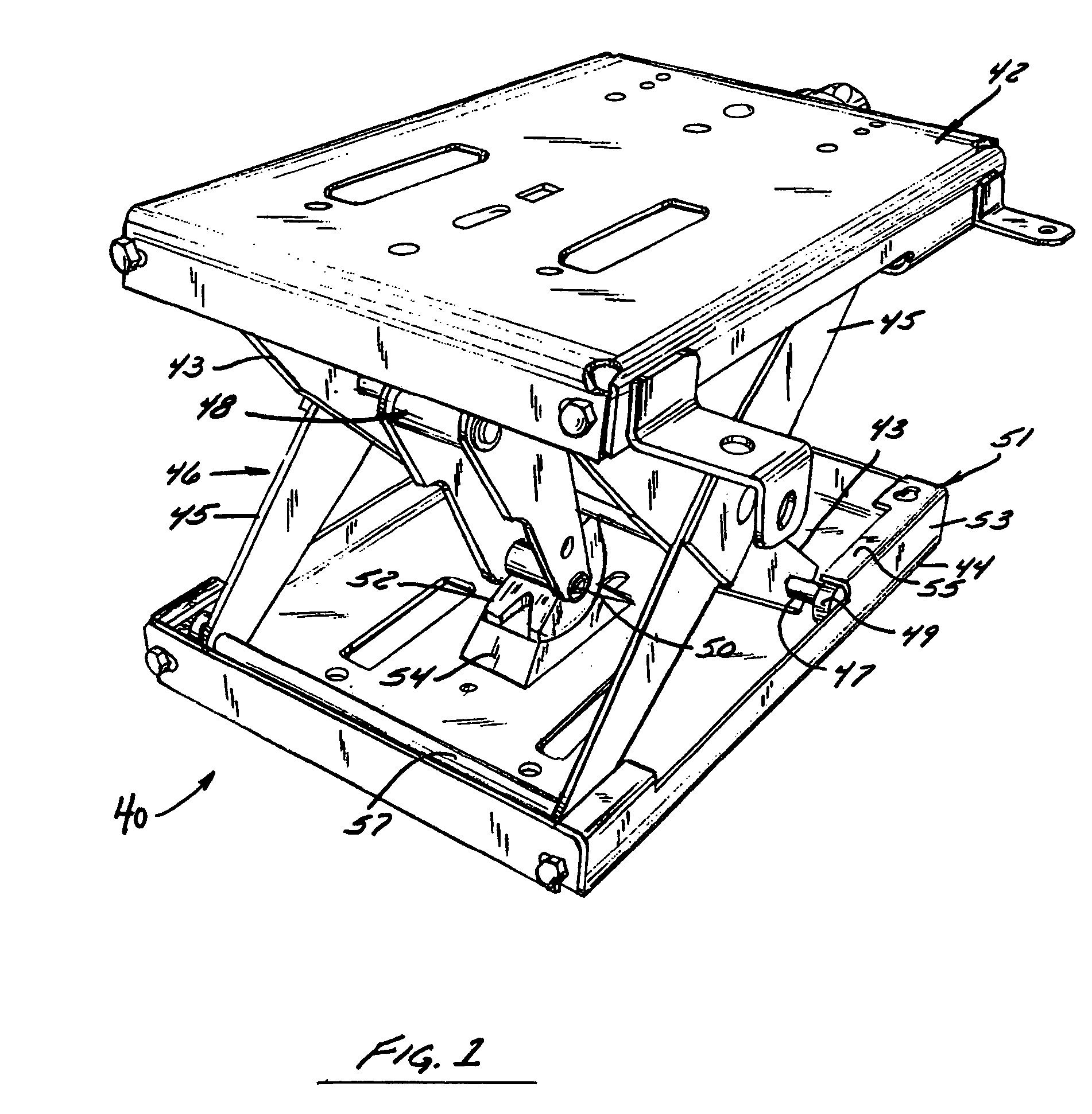
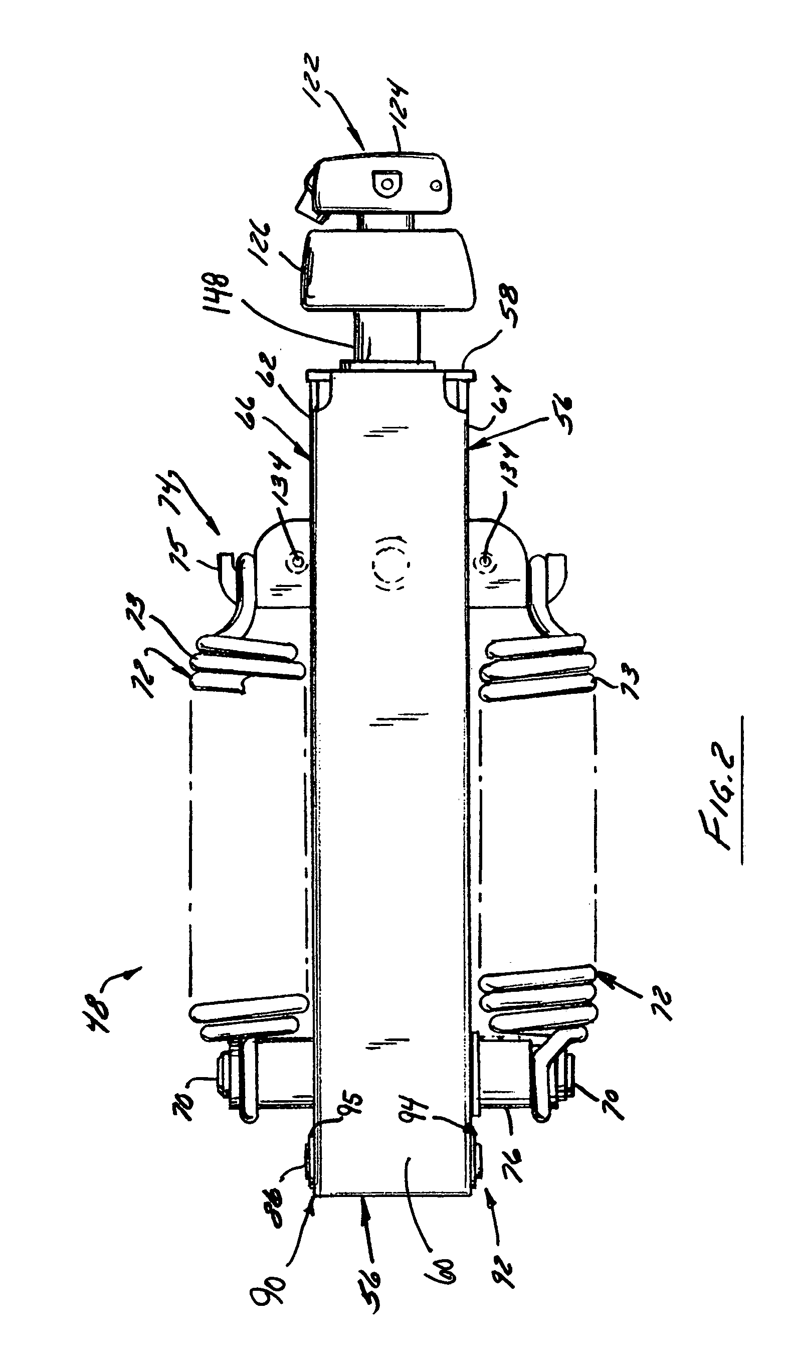
[0078]FIG. 1 illustrates a preferred embodiment of a seat suspension 40 of the invention that has a seat platform 42 and a base or ground 44 between which is disposed a linkage arrangement 46 and a suspension cartridge 48. The suspension cartridge 48 is of self-contained and modular construction to facilitate assembly and installation. The suspension cartridge 48 preferably is equipped with at least one outwardly extending arm 50 that carries a roller 52. The suspension cartridge 48 absorbs energy while providing at least weight adjustment capability. In the preferred embodiment shown in FIG. 1, the suspension cartridge 48 provides both height and weight adjustment capabilities. In the preferred embodiment shown in FIG. 1, the roller 52 cooperates with a contoured cam 54 during suspension operation.

[0079]In the preferred seat suspension embodiment shown in FIG. 1, the linkage arrangement 46 preferably comprises a scissors linkage arrangement, but is not intended to be limited to a s...


PUM


Abstract

A vehicle seat suspension that includes a suspension cartridge which houses suspension components that includes one or more of the following: one or more biasing elements, a suspension arm arrangement, a damper arrangement, a height adjust assembly, and a weight adjust assembly. In one preferred embodiment, the cartridge includes all of these. The suspension can include a truncated roller that provides a larger effect of radius. The suspension can also include a cam upon which a suspension roller rides that increases maximum suspension stroke while minimizing collapsed suspension height. The suspension can also include a damper that is oriented so as to provide a nearly linear response over all regions of suspension stroke or travel.

Description

CROSS REFERENCE TO RELATED APPLICATION[0001]This application claims priority from U.S. Provisional Patent Application Ser. No. 60 / 426,957, which was filed on Nov. 15, 2002, the entirety of which is expressly incorporated herein.FIELD OF INVENTION[0002]The present invention is directed to a vehicle seat suspension and more particularly to a vehicle seat suspension that is well-suited for use in off-road vehicles.BACKGROUND OF INVENTION[0003]Most manufacturers of seat suspensions have sold, or are currently selling, a conventional bell crank mechanical suspension system. The main components of this type of seat suspension typically include:[0004]Two support brackets welded to the top plate (e.g. the seat platform);[0005]Two extension springs;[0006]A welded bell crank sub-assembly that includes two bell crank arms, a bearing tube between the two bell crank arms, and a spring mounting shaft fixed to the bell crank arms;[0007]A spring hanger bracket;[0008]A tension adjust shaft;[0009]A k...

Claims


Application Information

Patent Timeline
Patent Type & Authority Patents(United States)
IPC IPC(8): F16M13/00B60N2/50B60N2/54
CPCB60N2/502B60N2/544B60N2/508B60N2/505
Inventor HILL, KEVINDAHLBACKA, BRUCE
Owner MILSCO LLC
Learn More