Box beam terminals

a technology of box beams and terminals, which is applied in the direction of machine supports, other domestic objects, and ways, can solve the problems of violent vehicular rollover, severe injury to the occupants, and intense deceleration of the vehicle, and achieve the effect of widening the opening

Inactive Publication Date: 2007-03-06
TEXAS A&M UNIVERSITY
View PDF8 Cites 44 Cited by
  • Summary
  • Abstract
  • Description
  • Claims
  • Application Information

AI Technical Summary

Benefits of technology

[0012]In some described embodiments, the box beam member presents a closed square or rectangular cross-section. The chute portion of the impact head is formed by a pair of side plates that grip opposite corners of the box beam member. During an end-on impact to the impact head, the box beam member is bent by the curved plate portion of the impact head. Preferably, the box beam member is also compressed at opposite corners by a flattening section in the impact head and the beam member flattened out to some degree to assist bending.
[0013]In other described embodiments, the box beam member has an open square, rectangular, or trapezoidal cross-section wherein there is an opening in one side of the cross-section. In other words, the box beam member has an “open” cross-section. The chute portion of the impact head includes an angular, or peaked,

Problems solved by technology

Early guardrail installations lacked any safety termination at the upstream ends, and occasionally, impacting vehicles became impaled on the ends causing intense deceleration of the vehicle and severe injury to the occupants.
In some reported cases, the guardrail end penetrated into the occupant compartment of the vehicle with fatal results.
This method has some recognized disadvantages, including an unintended possibility of ramping an approaching vehicle off the ground during a collision, which can result in a violent vehicular rollover.
H

Method used


Image

  • Box beam terminals
  • Box beam terminals
  • Box beam terminals

Examples


Embodiment Construction

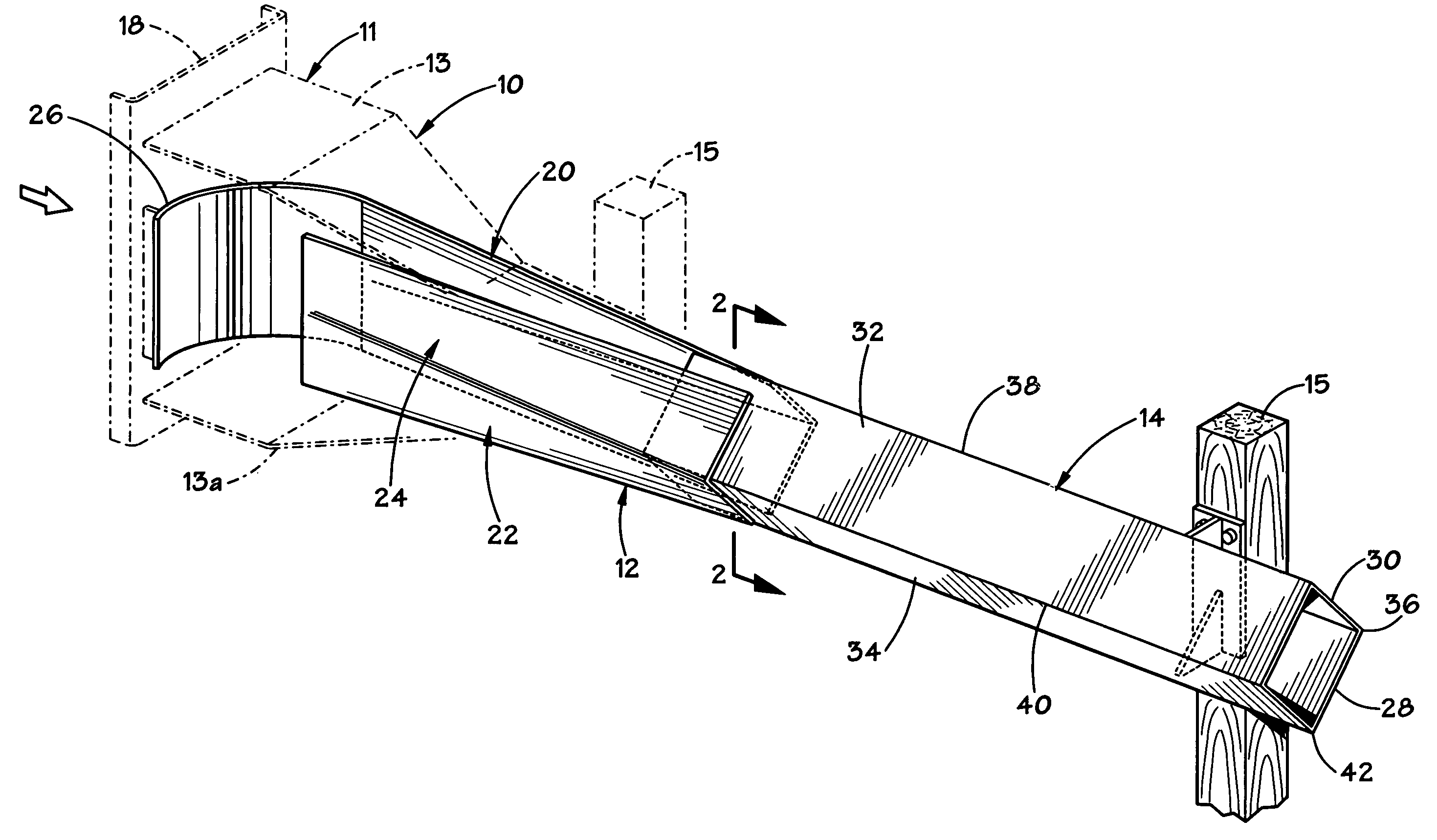
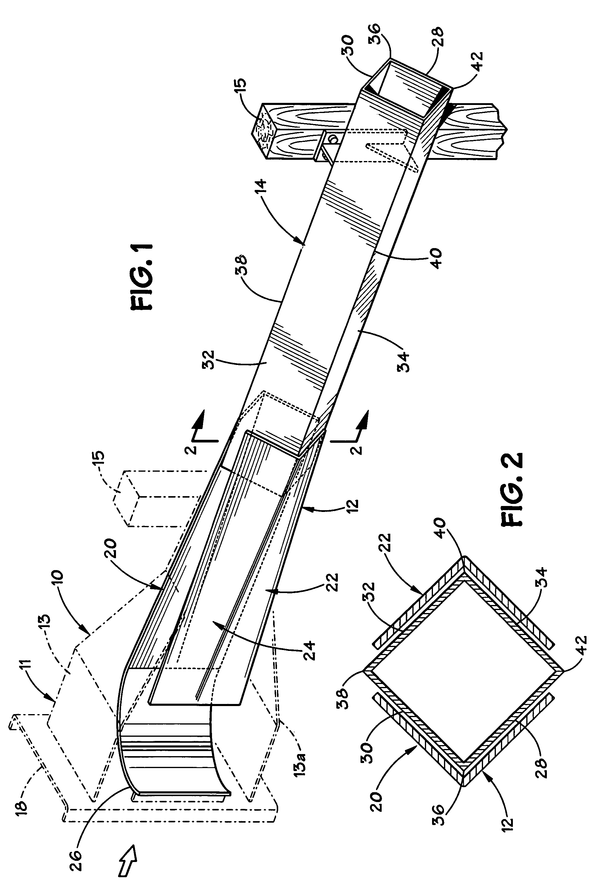
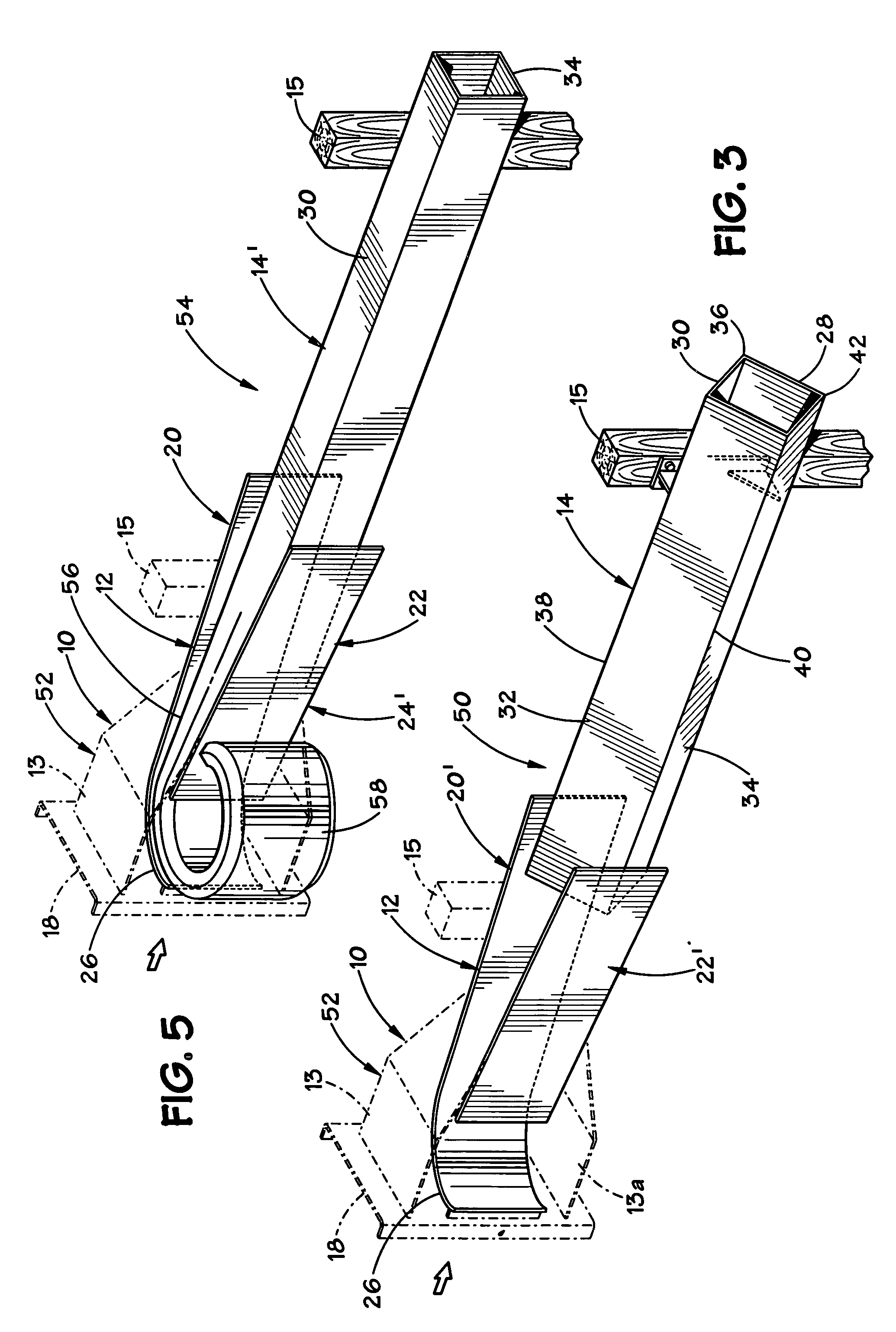
[0042]The concept of the invention is largely described through discussion of currently preferred and exemplary guardrail installations. The present invention provides end treatments for improved safety relating to end-on impacts to box-beam style guardrail installations.

[0043]Referring first to FIGS. 1 and 2, there is shown a first exemplary embodiment for a box-beam style terminal 10. The terminal 10 includes an impact head 11 having an elongated chute 12 that is disposed at the upstream end of a box beam rail member 14. As used herein, the term “upstream” refers to the direction from which an impacting vehicle would be expected to approach. The term “downstream” refers to the opposite direction, i.e., the direction toward which an impacting vehicle would be expected to travel. The terminal 10 includes both the impact head 11 and the rail member 14. The rail member 14 is a box beam rail member having a tubular, non-solid cross section. It is noted that the rail member 14 is suppor...


PUM


Abstract

Guardrail installation designs are described that incorporate a box beam rail as the structural rail member. The box beam rail member may have an open cross-section or a closed cross-section. An impact head is provided to bend and deflect the rail member during an end-on collision, allowing the rail member to be deflected away from the roadway and out of the path of an end-on impacting vehicle. The impact head includes a striking face and a chute portion that receives the box beam rail member therewithin. In addition to bending and deflecting the rail member, the impact head may also include a flattening section for flattening the rail member.

Description

CROSS-REFERENCE TO RELATED APPLICATIONS[0001]This application claims the priority of provisional patent application Ser. No. 60 / 306,970 filed Jul. 20, 2001.BACKGROUND OF THE INVENTION[0002]1. Field of the Invention[0003]The invention relates to box beam style guardrail installations and safety end treatments for such installations. The invention also relates to methods of use associated with these devices.[0004]2. Description of the Related Art[0005]Guardrail installations are used along roadways to prevent errant vehicles from leaving a roadway wherein they may encounter hazards that are a substantial danger to them. In its simplest form, the guardrail installation features a horizontally disposed rail member that is supported above the ground by a series of support posts. The rail member is most commonly provided by longitudinal segments of corrugated sheet steel having a W-shaped cross-section. Other corrugated rail members, such as the “thrie-beam” are used in some situations. A...

Claims


Application Information

Patent Timeline
IPC IPC(8): E01F15/10F16L3/08E01F15/14
CPCE01F15/143
Inventor BUTH, C. EUGENEBLIGH, ROGER P.ALBERSON, DEAN C.BULLARD, JR., LANCE D.ROSS, JR., HAYES E.ABU-ODEH, AKRAM
Owner TEXAS A&M UNIVERSITY
Why Eureka
Try Eureka