Drawer slide

a technology for sliding tables and drawers, applied in drawers, furniture parts, domestic applications, etc., can solve the problems of only being corrected, unable to meet the needs of users, and only being able to adjust, so as to achieve simple and cost-effective design, improve quality, and reduce maintenance and repair.

a technology for sliding tables and drawers, applied in drawers, furniture parts, domestic applications, etc., can solve the problems of only being corrected, unable to meet the needs of users, and only being able to adjust, so as to achieve simple and cost-effective design, improve quality, and reduce maintenance and repair.

US7185959B2Inactive Publication Date: 2007-03-06GRASS GMBH

Image

  • Drawer slide
  • Drawer slide
  • Drawer slide

Examples


Embodiment Construction

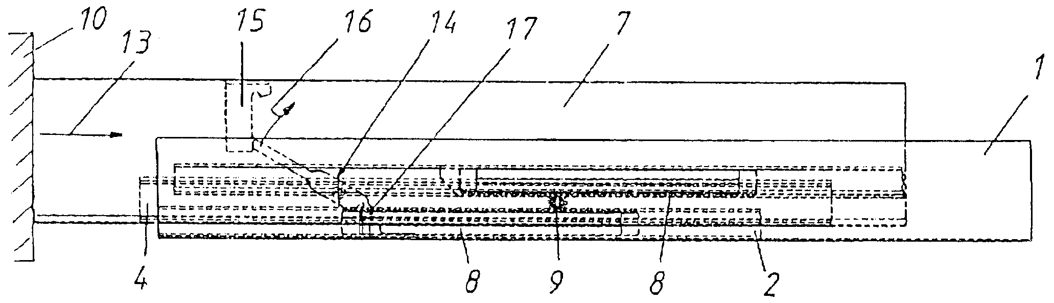
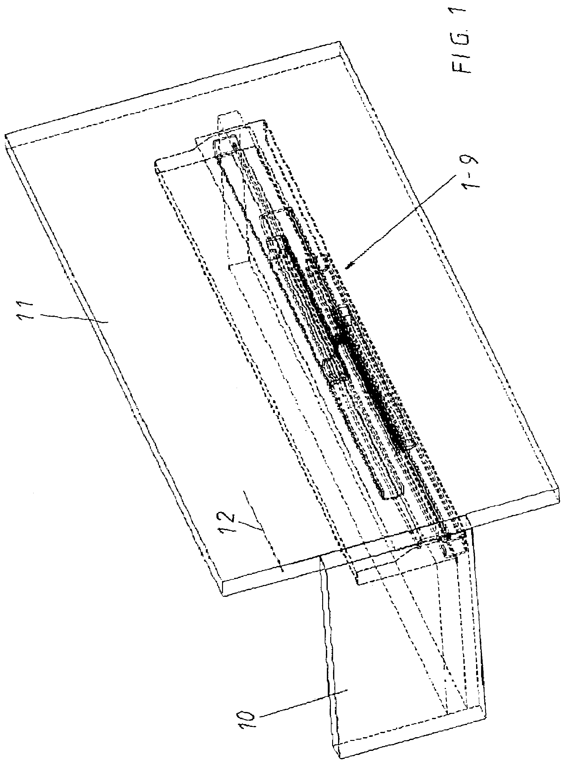
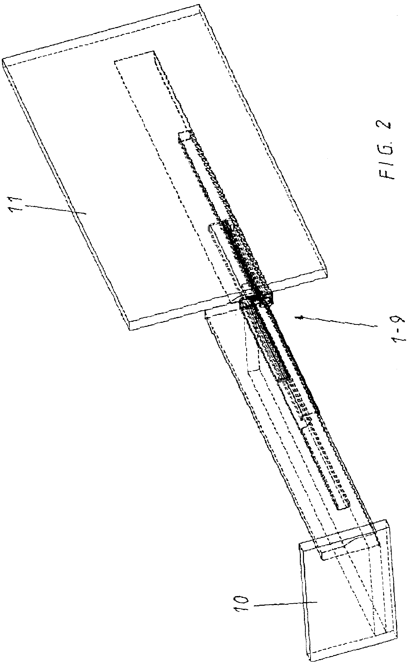
[0046]FIGS. 1–3 show general perspective sectional views of a full extension drawer slide, which should clarify the systemic synchronous running error.

[0047]FIG. 1 shows the drawer in a completely closed (original) position, for example, after the depth gap has been adjusted between the drawer's front panel and the front face side of the cabinet, which is usually set to approximately 1 mm.

[0048]FIG. 2 shows the representation of the full extension drawer when it is completely pulled out of the cabinet; whereby, the whole drawer, together with the décor, projects out of the cabinet opening. A relative movement has taken place between, respectively, the rails (that are working together) by the glide carriage.

[0049]FIG. 3 shows the drawer again in its closed state, after it was again pushed into the cabinet from its ‘open’ position, according to FIG. 2. The front gap increases from its previous 1 mm by the synchronous error and becomes, for example, 3 to 4 mm. This synchronous error is...


PUM


Abstract

The invention concerns a drawer slide with compensation of synchronous running errors of slide rails (equalize the errors of the relative positions of the slide rails to each other), having on each of the two side of the drawer a rail system, that has a cabinet rail fastened directly or indirectly by a cabinet angle on a cabinet body and is held directly or indirectly linearly movable by a linear bearing by a center rail on a drawer rail, which is connected directly or indirectly by a décor with the drawer; whereby a compensation mechanism is provided that has a compensation lever, that is connected by a pivot bearing directly or indirectly by a cabinet angle or linear bearing or décor with one of the rails, and during its turning at the end of each drawer closing cycle, reaches a positive / form-fitting position with stops, that directly or indirectly are connected by a cabinet angle or linear bearing or décor with the remaining rails and, thus, ensures each drawer closing is automatic, guided and has equalized any synchronous running error.

Description

FIELD OF THE INVENTION[0001]The invention concerns a drawer slide with compensation of the synchronous running errors of the slide rails that equalize the errors of the relative positions of the slide rails to each other, according to the characterizing clause of the independent claims.BACKGROUND OF THE INVENTION[0002]Drawer slide with synchronization of the slide rail runs are made known, for example, by DE-40 19 124 C2, DE-42 26 812 A1 and DE-92 19 064 U1, that refer back to the same applicant.[0003]DE-42 26 812 A1 and DE-92 19 064 U1, which refers back to it, make known a drawer slide with full extension and a traction mechanism, which consists of a drawer rail, a center rail and a cabinet rail, so that a load transferring carriage is located between the rails. In order to achieve a synchronous shift between the center rail when the drawer rails slide, a traction mechanism (rope, chain, etc.) is provided, which runs over the deflection rollers on the center rail. The upper trunk ...

Claims


Application Information

Patent Timeline
06 Mar 2007
Publication
US7185959B2
IPC
A47B88/00; A47B88/04
CPC
A47B88/04; A47B2210/0078; A47B88/44; A47B88/467; A47B88/46; A47B88/40
Inventors
MUELLER, WOLFGANG; GEHRER, HARALD