Method and apparatus for a variable intensity pulsed L.E.D. light

a pulsed light and variable intensity technology, applied in the field of lighting, can solve the problems of reducing light output, dimming the light, dropping and dissipating the corresponding power loss of the resistor, and achieve the effect of low weigh

Inactive Publication Date: 2007-03-06
LEMAIRE ILLUMINATION TECH +1
View PDF53 Cites 137 Cited by
  • Summary
  • Abstract
  • Description
  • Claims
  • Application Information

AI Technical Summary

Benefits of technology

[0007]Some embodiments provide a method of providing changeable illumination of such compact size and low weight as to be suitable for single-handed portable operation by a user. The method includes providing one or more LEDs having a first characteristic color spectrum output and one or more LEDs having a second characteristic color spectrum output, wherein the first characteristic color spectrum output is different from the second characteristic color spectrum output, selectively applying pulsed power from a DC voltage source to the LEDs, wherein the pulses are of high-enough frequency such that the human eye does not perceive the pulses, and changing a pulse characteristic of the pulsed power in order to change a proportion of light output having the first characteristic color spectrum output to that having the second characteristic color spectrum output.
[0009]The present invention provides a method and apparatus for an L.E.D. flashlight or other LED illumination source. In one embodiment, a flashlight is described. The flashlight includes a flashlight housing suitable for receiving therein and / or mounting thereon at least one DC voltage source such as a battery. The flashlight also includes a light-emitting diode (LED) housing connected to the flashlight housing, the LED housing including a first plurality of LED units that each emit light and have a reflector for collimating the emitted light forwardly therefrom generally along an LED optical axis, the first plurality of LED units including at least seven individual LED units. The flashlight also includes a first electrical circuit that selectively applies power from the DC voltage source to the LED units, wherein the flashlight is of such compact size and low weight as to be suitable for single-handed portable operation by a user, the flashlight further having a purpose of providing general-purpose illumination.
[0014]Another aspect of the present invention provides a flashlight including: (a) a flashlight housing, the housing being suitable for at least one of receiving therein and mounting thereon at least one DC voltage source that includes at least one battery cell; (b) a light-emitting diode (LED) housing connected to the flashlight housing, the LED housing including one or more first LED units that each emit light and have a reflector for collimating the emitted light forwardly therefrom generally along an LED optical axis; and (c) a first electrical circuit that selectively applies power from the DC voltage source to the LED units, the first electrical circuit further including a control circuit for maintaining a predetermined light output level of the LED units as a charge on the battery cell varies; wherein the flashlight is of such compact size and low weight as to be suitable for single-handed portable operation by a user, the flashlight further having a purpose of providing general-purpose illumination.
[0017]Another aspect of the present invention provides a method of providing general-purpose illumination of such compact size and low weight as to be suitable for single-handed portable operation by a user, including the steps of: (a) providing one or more first LED units that each emit light and have a reflector for collimating the emitted light forwardly therefrom generally along an LED optical axis; (b) selectively applying power from a DC voltage source to the LED units; and (c) maintaining a predetermined light output level of the LED units as a charge on the battery cell varies by controlling the step (b).

Problems solved by technology

This decreased available voltage across the given load causes reduced light output, gradually dimming the light as the battery charge depletes.
This voltage drop and corresponding power loss in the resistor is dissipated as waste heat, which is inefficient for a flashlight which should be designed to emit light.
In addition, it is awkward or difficult to determine the amount of remaining charge in a battery cell, generally requiring removal of the battery from the flashlight in order to measure the remaining charge.
In addition, the cost of a separate measurement device can be a negative for this market.

Method used


Image

  • Method and apparatus for a variable intensity pulsed L.E.D. light
  • Method and apparatus for a variable intensity pulsed L.E.D. light
  • Method and apparatus for a variable intensity pulsed L.E.D. light

Examples


case 110

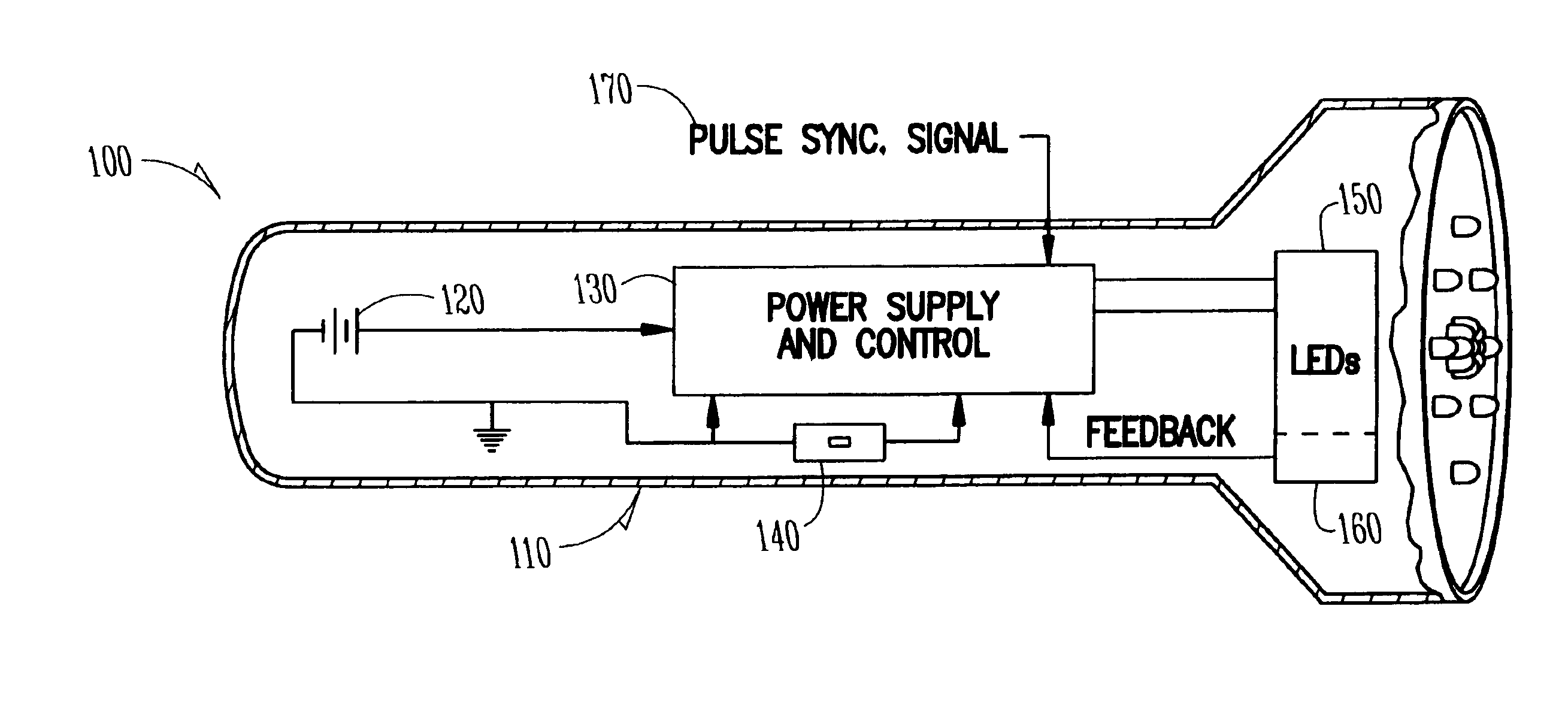
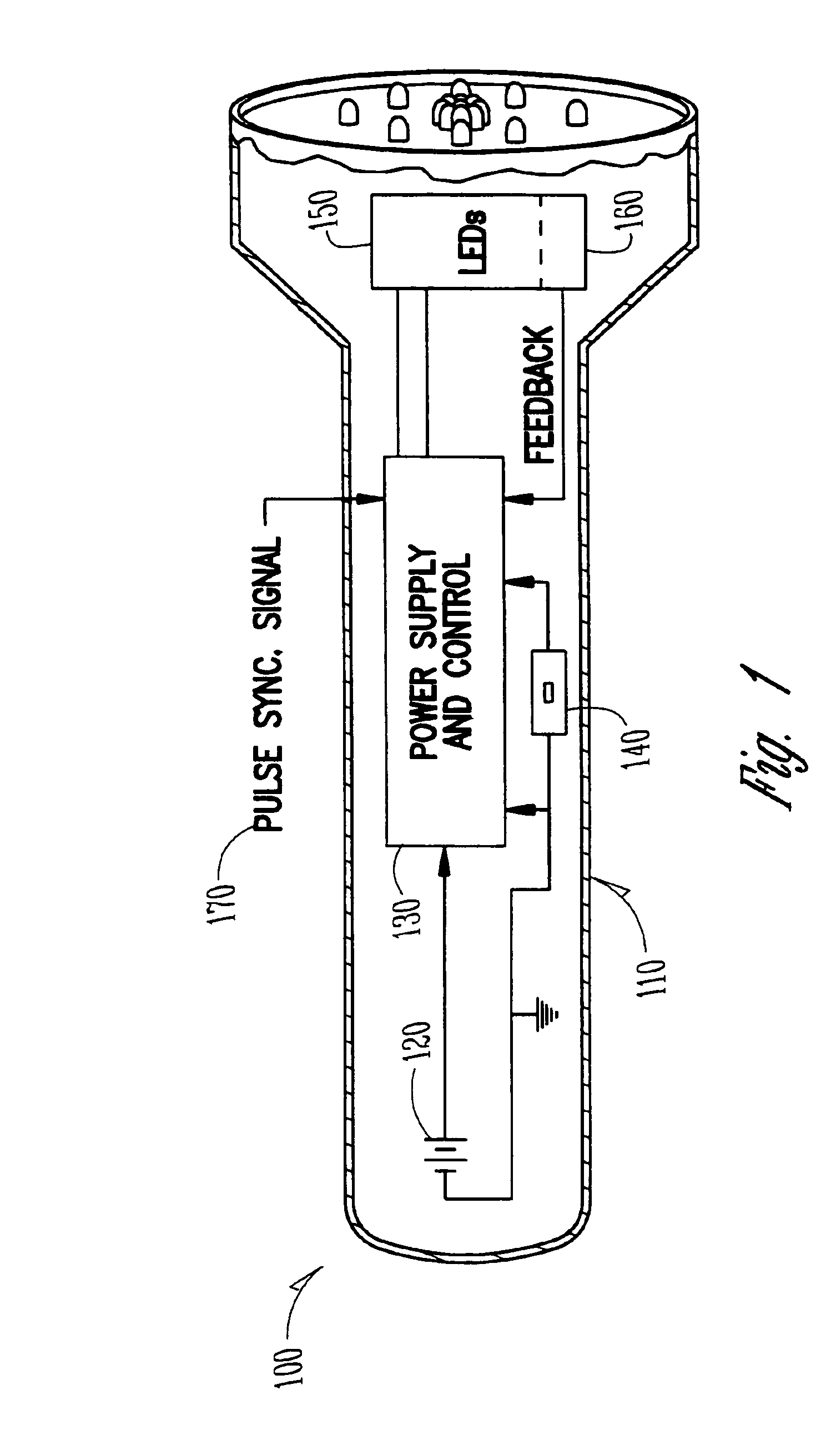
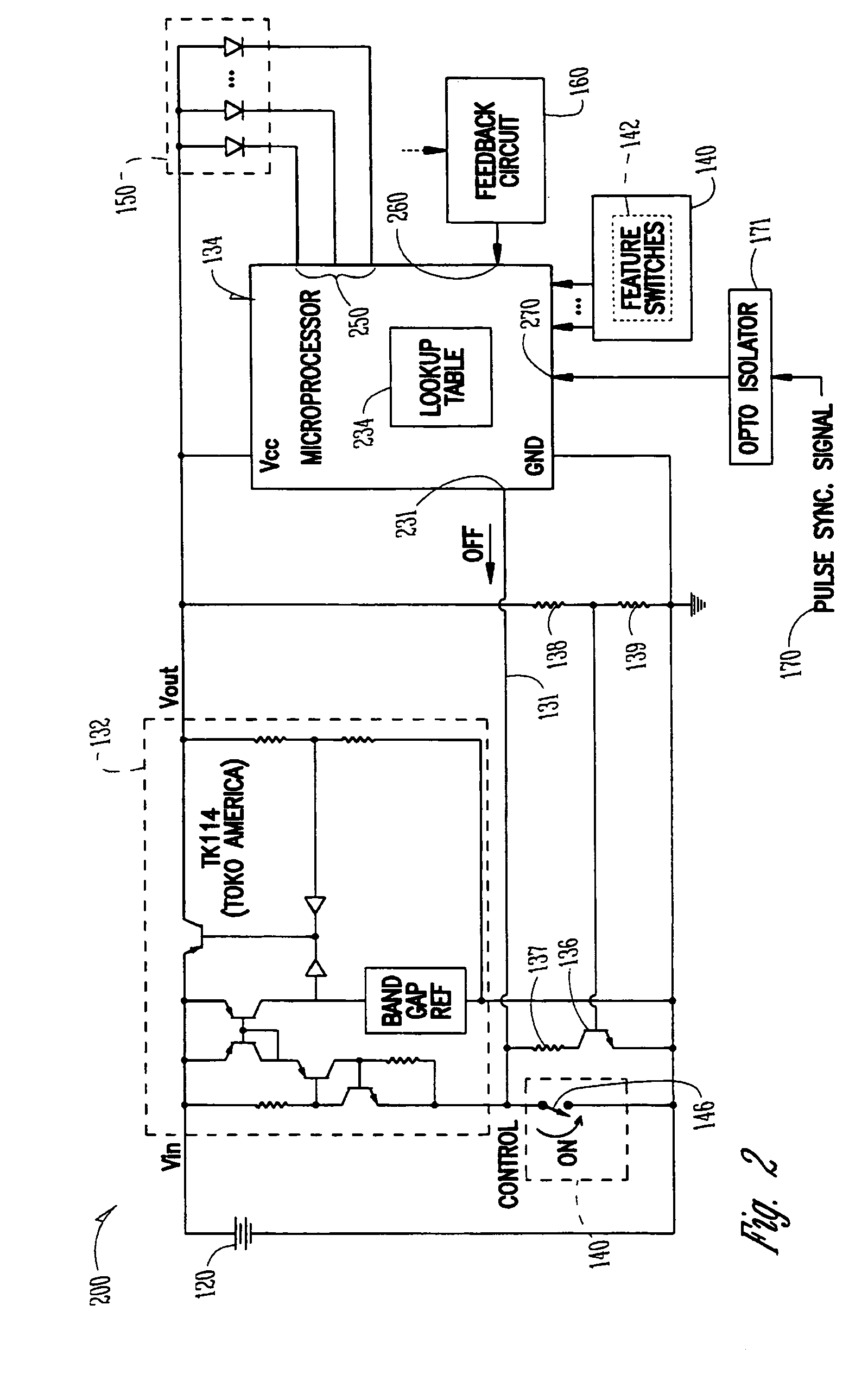
[0045]Case 110 is any convenient size and shape, and is typically designed to hold the battery, provide a suitable grip to be handheld, and provide a housing for the circuitry and LEDs. In one embodiment, battery 120 includes one or more cells which can be any suitable technology such as alkaline dry cells or rechargeable cells. Alternatively, other portable DC electrical power sources can be used as desired in place of battery 120. Power supply and control circuit (PSCC) 130 responds to a switch circuit to apply electrical power from battery 120 to LEDs 150, controlled in order to prevent overloading and premature destruction of LEDs 150 while minimizing power dissipation within PSCC 130, thus maximizing battery life, providing the desired accuracy or level of the amount of light emitted at different battery voltages or other environmental conditions that would otherwise vary the light output. Switch circuit 140 allows the user to control various flashlight functions such as, for e...


PUM


Abstract

Improved method and apparatus for hand-held portable LED illumination. The illumination source includes a plurality of LEDs, and an electrical circuit that selectively applies power from the DC voltage source to the LED units, wherein the illumination source is suitable for handheld portable operation. In some embodiments, the electrical circuit further includes a control circuit for changing a proportion of light output having the first characteristic color spectrum output to that having the second characteristic color spectrum output, and that drives the LEDs with electrical pulses at a frequency high enough that light produced has an appearance to a human user of being continuous rather than pulsed. Still another aspect provides an illumination source including a housing including one or more LEDs; and a control circuit that selectively applies power from a source of electric power to the LEDs, thus controlling a light output color spectrum of the LEDs.

Description

RELATED APPLICATIONS[0001]This application is a Divisional under 37 C.F.R. 1.53(b) of U.S. application Ser. No. 10 / 299,609 filed Nov. 18, 2002 (U.S. Pat. No. 6,808,287); which is a continuation of U.S. application Ser. No. 09 / 978,760 filed Oct. 16, 2001 (U.S. Pat. No. 6,488,390); which is a continuation of U.S. application Ser. No. 09 / 627,268 filed Jul. 28, 2000 (U.S. Pat. No. 6,305,818); which is a divisional of U.S. application Ser. No. 09 / 044,559 filed Mar. 19, 1998 (U.S. Pat. No. 6,095,661); which applications are incorporated herein by reference.FIELD OF THE INVENTION[0002]This invention relates to the field of lighting, and more specifically to a method and apparatus of controlling and powering a solid-state light source such as a light-emitting diode or LED, for a portable battery-powered flashlight.BACKGROUND OF THE INVENTION[0003]There is a widespread need for hand-held flashlights and lanterns. One common flashlight includes a two-cell battery for power, an incandescent la...

Claims


Application Information

Patent Timeline
Patent Type & Authority Patents(United States)
IPC IPC(8): F21L4/02H04B10/50H04B10/564H04N5/235H05B44/00
CPCF21L4/027H04B10/502H04B10/564H04N5/2354H05B33/0803H05B33/0812H05B33/0818H05B33/0863H05B33/0869H05B33/089Y10S362/802Y02B20/343Y02B20/346Y10S362/80F21Y2101/02F21Y2115/10H05B45/22H05B45/395H05B45/20H05B45/50Y02B20/30H05B45/32H05B45/12H04N23/74
Inventor LEBENS, GARY A.BOURN, CHARLES T.LEMAIRE, CHARLES A.
Owner LEMAIRE ILLUMINATION TECH
Why Eureka
Try Eureka