Pole connector assembly and method for racks and shelving

a technology of pole connectors and assemblies, applied in the direction of rod connections, filing appliances, couplings, etc., can solve the problems of unreliable conventional pole connector devices and assemblies, lack of one or more aspects of pole connector devices, slow assembly and disassembly, etc., to achieve reliable and strong pole connection, simple and inexpensive manufacturing, and additional stability

Inactive Publication Date: 2007-03-06
SPG INT
View PDF48 Cites 85 Cited by
  • Summary
  • Abstract
  • Description
  • Claims
  • Application Information

AI Technical Summary

Benefits of technology

[0015]In some embodiments of the present invention, the inserts each have a cap portion that is preferably larger than the inner diameter of the pole sections being connected and that preferably abuts the end of a pole section. Although the inserts do not require a cap portion, this feature provides additional stability to the pole connection assembly. Also, the cap portion (e.g., a peripheral edge of the cap portion) can be chamfered, beveled, or otherwise recessed so that the pole connector assembly has a circumferential groove at the pole section interface to which shelves and racks can be connected.
[0016]The elements making up the pole

Problems solved by technology

However, existing pole connector devices fail to balance these design considerations well, invariably resulting in pole connector device designs that are lacking in one or more respects.
Conventional pole connector devices and assemblies are often unreliable, heavy, slow to assemble and disassemble, expensive to manufacture, and difficult to properly align and adjust.
The machining required for threading conventional pole inserts is expensive and can represent a significant part of the cost of a shelving and rack system.
Although a number of alternatives exist to machining threads into the pole inserts and pole section ends (e.g., casting or molding threads), each of these alternatives adds significant costs to the manufacturing process in one or more ways, such as through expensive molds and molding machinery, etc.
The use of threaded pole inserts can also add significant time to the pole assembly process, especially when several pole sections and several rack or shelf systems need to be assembled.
Such inserts and pole sections can be difficult to thread together, and in some cases may not properly align to form a straight pole.
In such cases, threade

Method used


Image

  • Pole connector assembly and method for racks and shelving
  • Pole connector assembly and method for racks and shelving
  • Pole connector assembly and method for racks and shelving

Examples


Embodiment Construction

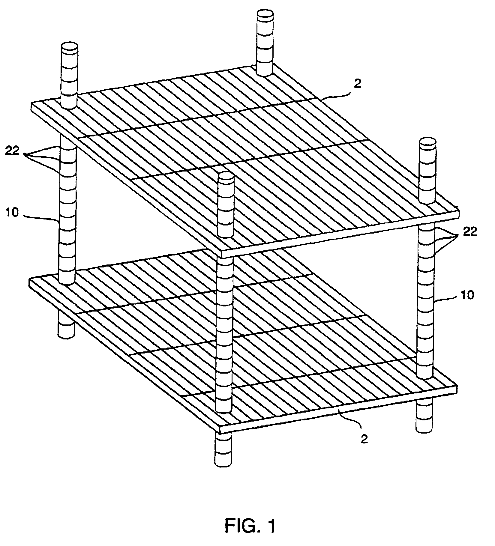
[0034]The present invention is described in terms of its application to poles for adjustable and non-adjustable shelves and racks such as that shown in FIG. 1. An example of such a shelf assembly is disclosed in U.S. Pat. No. 4,852,501 issued to Olson et al., the disclosure of which is incorporated herein by reference insofar as it relates to shelf assemblies and adjustable shelf assemblies. However, the present invention can be employed in any application in which two pole sections must be connected in an end-to-end fashion.

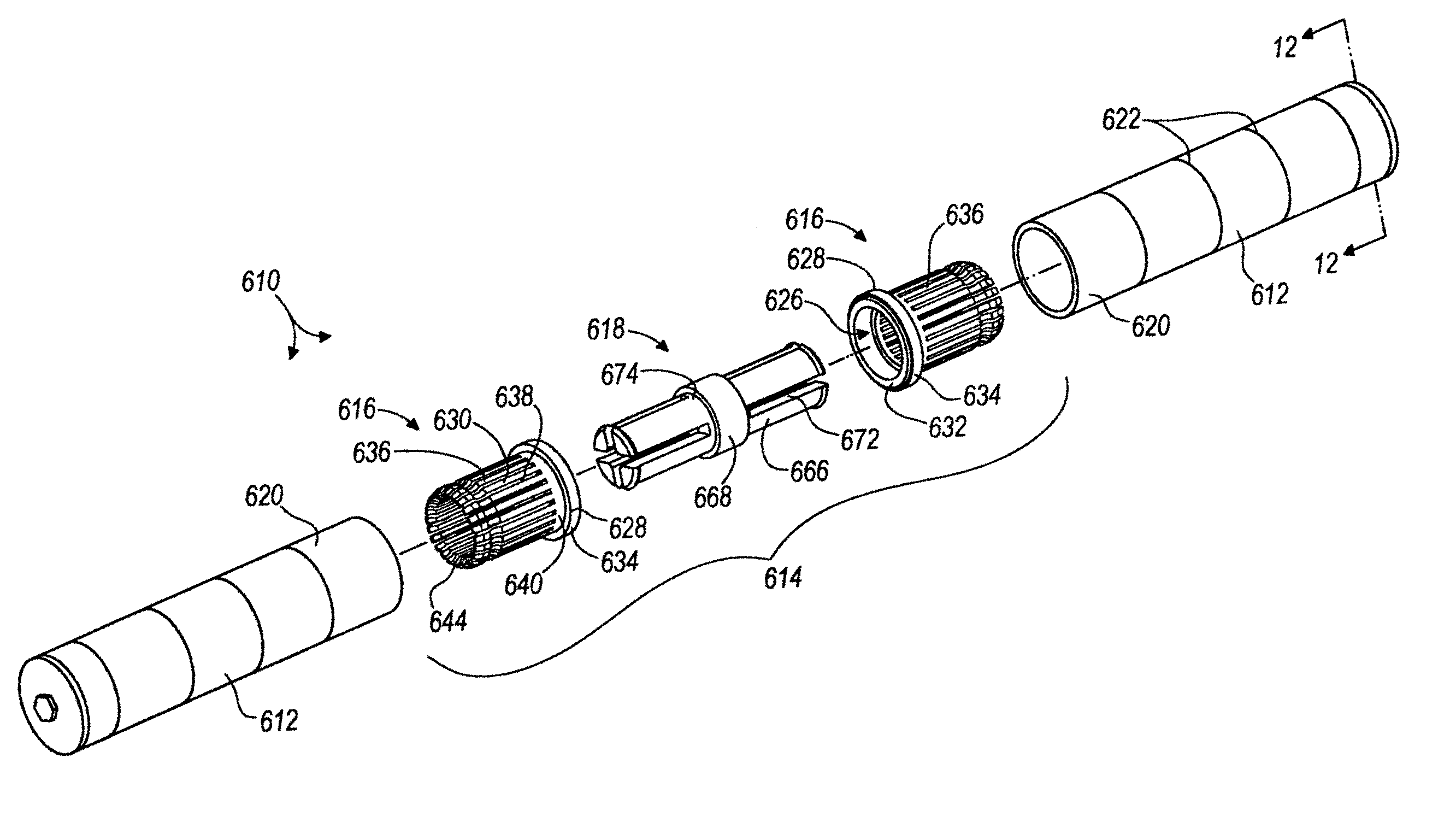
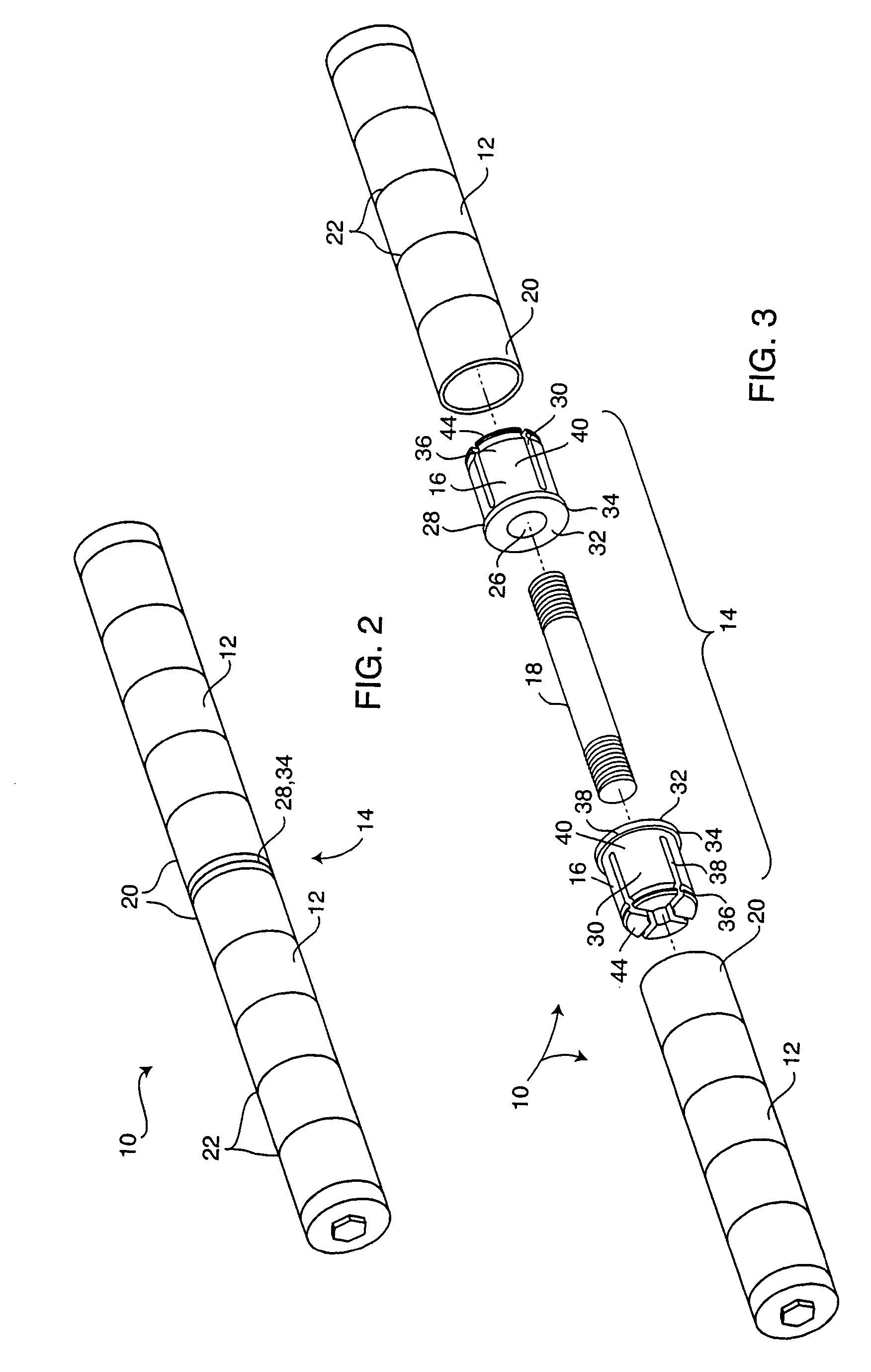
[0035]FIGS. 2 and 3 illustrate a pole according to one preferred embodiment of the present invention. The pole 10 has at least two pole sections 12 connected in end-to-end fashion as will be described in greater detail below. Although the pole 10 in FIGS. 2 and 3 has only two pole sections 12, it should be noted that a pole 10 having any number of pole sections 12 and pole section lengths is possible according to the present invention.

[0036]FIGS. 3 and 5 illustr...


PUM


Abstract

A pole connector assembly for connecting adjacent pole sections in order to construct a pole. In some embodiments, these pole connector assemblies have two inserts connected together by a fastener. Each of the two inserts can be received within an open end of a respective pole section. The fastener can be received within an aperture in each of the inserts in order to connect the pole sections together. In some embodiments, each insert can have at least one projection that extends into the pole section within which the insert is received. The fastener can limit the at least one projection from being inwardly deflected in order to secure the insert within the corresponding pole section. In other embodiments, the fastener can have at least one deformable portion to allow the fastener to secure the insert within the corresponding pole section.

Description

CROSS-REFERENCE TO RELATED APPLICATION[0001]This is a continuation-in-part of U.S. patent application Ser. No. 10 / 085,179 filed on Feb. 27, 2002, now U.S. Pat. No. 6,626,605 the entire disclosure of which is incorporated herein by reference.FIELD OF THE INVENTION [0002]The present invention relates to pole connector assemblies and devices, and more particularly to pole connector assemblies and devices for joining support post sections used in adjustable racks, shelving, and similar applications.BACKGROUND OF THE INVENTION [0003]Many existing shelving and rack systems are constructed of one or more poles connected to one or more shelves or racks. In some cases, the shelves or racks can be adjustably connected to the poles at different heights. Also, each pole often includes two or more pole sections that are connected in an end-to-end fashion by pole connector devices or assemblies. Pole connector devices and the poles assembled with such devices are preferably strong, lightweight, e...

Claims


Application Information

Patent Timeline
IPC IPC(8): B42F13/00F16B7/02F16B7/04F16B12/40
CPCF16B7/025F16B7/0413F16B12/40Y10T403/69Y10T403/7091Y10T403/7054F16B2012/403
Inventor DEAN, DOUGLAS R.WALTERS, PETERJOHN R. C.
Owner SPG INT
Why Eureka
Try Eureka