Axial flow stream turbines

a technology of axial flow and stream turbines, which is applied in the direction of machines/engines, liquid fuel engines, lighting and heating apparatus, etc., can solve the problem of outer shroud parts moving with the casing

Active Publication Date: 2007-03-06
GENERAL ELECTRIC TECH GMBH
View PDF32 Cites 24 Cited by
  • Summary
  • Abstract
  • Description
  • Claims
  • Application Information

AI Technical Summary

Benefits of technology

[0018]The at least one impulse turbine stage may follow a control stage that is an impulse turbine stage, the control stage comprising at least one steam inlet passage for directing steam onto an annular row of moving blades, and valve means for controlling the flow of steam into the turbine.

Problems solved by technology

A disadvantage of this arrangement is that the outer shroud portions move with the casing 28 as it expands and contracts.

Method used


Image

  • Axial flow stream turbines
  • Axial flow stream turbines
  • Axial flow stream turbines

Examples


Embodiment Construction

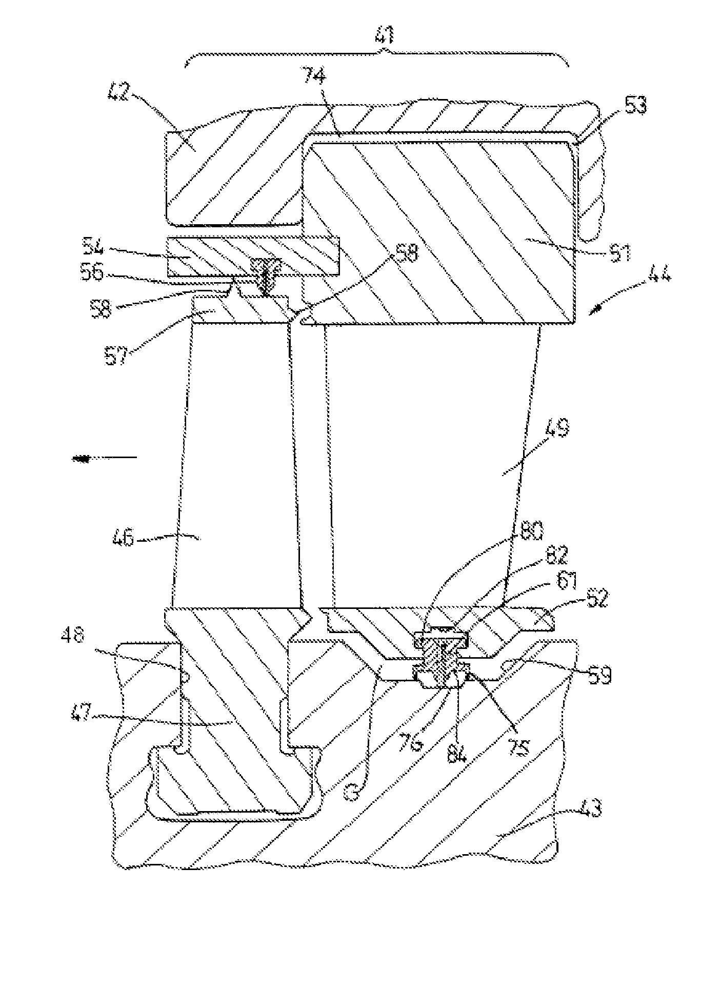
[0028]Referring to the drawings, FIG. 3A shows an impulse turbine stage 41 which is one of a plurality of such stages in a steam turbine comprising a turbine casing 42 surrounding a drum-type rotor 43. The turbine stage 41 comprises a static blade assembly 44 upstream of an annular row of moving blades 46 having root portions 47 held within a slot 48 in the periphery of the rotor 43. The static blade assembly 44 comprises an annular row of static blades 49 extending between a radially outer static ring 51 and a radially inner static ring 52, the radially inner side of which confronts the periphery of the rotor 43. Both rings 51 and 52 are segmented as necessary for manufacture, assembly and operation of the turbine.

[0029]The outer static ring 51 is housed in an annular chamber 53 which is formed in the casing 42 and is open towards the rotor 43, so that the outer ring 51 is axially located by the casing 42 but can move to a limited extent in the radial direction. The outer ring has ...


PUM


Abstract

A drum-type rotor carries an annular row of moving blades having root portions held within a slot in the periphery of the rotor. A turbine casing surrounds the rotor and carries a static blade assembly with an annular row of static blades which, together with the annular row of moving blades, constitutes an impulse turbine stage. The static blade assembly has a radially inner static ring confronting a periphery of the rotor with a seal acting therebetween. The static blade assembly has an outer static ring which has a substantially greater thermal inertia and stiffness then the inner static ring and is capable of sufficient radial sliding relative to the casing so as to accommodate relative thermal expansion and contraction of the outer static ring and the turbine casing.

Description

[0001]Priority is claimed to United Kingdom Patent Application No. GB 0311009.5, filed on May 13, 2003, and to United Kingdom Patent Application No. GB 0311008.7, filed on May 13, 2003. The entire disclosure of both applications is incorporated by reference herein.[0002]This invention relates to axial flow steam turbines that include one or more stages of the impulse type.BACKGROUND[0003]Steam is supplied to a turbine at high pressure and temperature from a boiler and the energy in the steam is converted into mechanical work by expansion through the turbine. The expansion of the steam takes place through a series of static blades or nozzles and moving blades. An annular row of static blades or nozzles and its associated annular row of moving blades is referred to as a turbine stage. After the steam has been expanded in a high pressure (HP) turbine, it is conventional to return it to the boiler for re-heating and then to return the steam to an intermediate pressure (IP) turbine, from...

Claims


Application Information

Patent Timeline
Patent Type & Authority Patents(United States)
IPC IPC(8): F01D11/08F01D11/00F01D11/12F01D1/04F01D1/16F01D9/00F01D9/04F01D11/02F01D17/10F01D25/24
CPCF01D25/26F01D11/001
Inventor BLATCHFORD, DAVID PAULBRIDGE, RICHARD MARTINHEMSLEY, PHILIP DAVIDHESKETH, ALANLORD, ADRIAN
Owner GENERAL ELECTRIC TECH GMBH
Why Eureka
Try Eureka