Methods and apparatus for cooling gas turbine engine components

a gas turbine engine and component cooling technology, applied in the field of gas turbine engines, can solve the problems of shortening the useful life of the component, reducing the overall efficiency of the engine, and reducing the ability to cool both the bond coating and/or the tb

Inactive Publication Date: 2007-03-06
GENERAL ELECTRIC CO
View PDF20 Cites 48 Cited by
  • Summary
  • Abstract
  • Description
  • Claims
  • Application Information

AI Technical Summary

Problems solved by technology

However, diverting air from the combustion process may decrease the overall efficiency of the engine.
Specifically, as the bond coating is exposed to elevated temperatures, it may degrade, and degradation of the bond coating may weaken the TBC / bond coating interface and shorten the useful life of the component.
However, the ability to cool both the bond coating and / or the TBC is limited by the cooling configurations used with the component.

Method used


Image

  • Methods and apparatus for cooling gas turbine engine components
  • Methods and apparatus for cooling gas turbine engine components
  • Methods and apparatus for cooling gas turbine engine components

Examples


Embodiment Construction

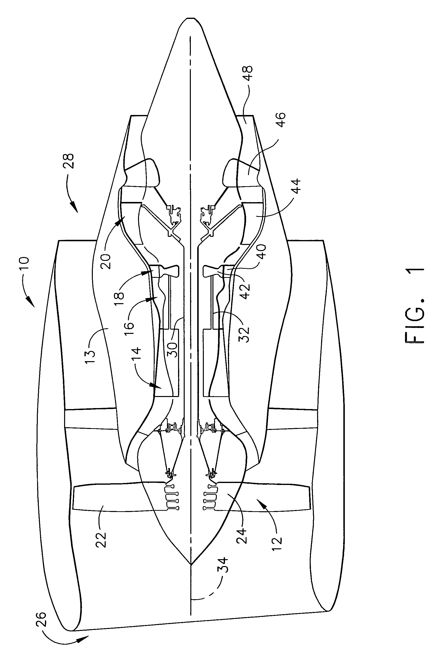
[0013]FIG. 1 is a schematic illustration of a gas turbine engine 10 including a fan assembly 12, a high pressure compressor 14, and a combustor 16. Engine 10 also includes a high pressure turbine 18 and a low pressure turbine 20. Fan assembly 12 includes an array of fan blades 22 extending radially outward from a rotor disc 24. Engine 10 has an intake side 26 and an exhaust side 28. Fan assembly 12 and turbine 20 are coupled by a first rotor shaft 30, and compressor 14 and turbine 18 are coupled by a second rotor shaft 32.

[0014]During operation, air flows generally axially through fan assembly 12, in a direction that is substantially parallel to a central axis 34 extending through engine 10, and compressed air is supplied to high pressure compressor 14. The highly compressed air is delivered to combustor 16. Airflow (not shown in FIG. 1) from combustor 16 drives turbines 18 and 20, and turbine 20 drives fan assembly 12 by way of shaft 30. Turbine 18 drives high-pressure compressor 1...


PUM

PropertyMeasurementUnit
diameteraaaaaaaaaa
diameteraaaaaaaaaa
diameteraaaaaaaaaa

Abstract

A method of cooling a gas turbine engine component having a perforate metal wall includes providing a plurality of pores in the wall, wherein the pores extend substantially perpendicularly through the wall, and wherein the pores are covered and sealed closed at first ends thereof by a thermal barrier coating disposed over a first surface of the wall, and providing a plurality of film cooling holes in the wall, wherein the holes extend substantially perpendicularly through the wall and the thermal barrier coating. The method also includes providing cooling fluid to the plurality of pores and the plurality of film cooling holes along a second surface of the wall, channeling the cooling fluid through the pores for back side cooling an inner surface of the thermal barrier coating, and channeling the cooling fluid through the holes for film cooling an outer surface of the thermal barrier coating.

Description

BACKGROUND OF THE INVENTION[0001]This invention relates generally to gas turbine engines, and more particularly, to methods and apparatus for cooling gas turbine engine components.[0002]Within known gas turbine engines, combustor and turbine components are directly exposed to hot combustion gases. As such, the components are cooled during operation by pressurized air channeled from the compressor. However, diverting air from the combustion process may decrease the overall efficiency of the engine.[0003]To facilitate cooling engine components while minimizing the adverse effects to engine efficiency, at least some engine components include dedicated cooling channels coupled in flow communication with cooling lines. In at least some known engines, the cooling channels may include cooling holes through which the cooling air is re-introduced into the combustion gas flowpath. Film cooling holes are common in engine components and provide film cooling to an external surface of the compone...

Claims


Application Information

Patent Timeline
Patent Type & Authority Patents(United States)
IPC IPC(8): F01D5/18
CPCF01D5/183F01D5/186F01D5/288F23R3/002F05D2300/611F23R2900/03041F05D2230/90
Inventor LEE, CHING-PANGBUNKER, RONALD SCOTTMACLIN, HARVEY MICHAELDAROLIA, RAMGOPAL
Owner GENERAL ELECTRIC CO
Why Eureka
Try Eureka