Attaching member to panel hole, and clamping tool

a technology for clamping tools and fixing members, which is applied in the direction of threaded fasteners, coupling device connections, screws, etc., can solve the problems of requiring considerable force for the release of couplings, and achieve the effect of convenient use as clamping tools, convenient operation and suitability

Active Publication Date: 2007-03-13
NIFCO INC
View PDF5 Cites 9 Cited by
  • Summary
  • Abstract
  • Description
  • Claims
  • Application Information

AI Technical Summary

Benefits of technology

[0014]By such constitution, the elastic coupling claw of the male part, which has the leg part inserted into the female part coupled and fixed in the panel hole, can be coupled in the panel hole through the pass-through part of the female part, whereby the male part can be fastened in the panel hole. Also, by rotating the male part thus fastened toward the uncoupled position inside the female part, the elastic coupling claw can be caused to be drawn into the female part, whereby the coupling between the male part and the panel hole is released and the male part can be removed from the panel hole while leaving the female part in the panel hole. Also, because such rotation toward the uncoupled position of the male part is impeded by the striking between the lock surface of the turn lock part and the lock receiving surface of the turn lock receiving part, the male part is not unexpectedly rotated so that the fastened state between the panel hole and the male part is released.
[0015]On the other hand, the rotation of the male part toward the uncoupled position can be assured by releasing the striking between the lock surface and the lock receiving surface by the elastic deformation. Although the elastic coupling claw of the male part is projected outward from the pass-through part of the female part in a state in which it is capable of being drawn into the female part by rotation toward the uncoupled position, because the turn lock part and the turn lock receiving part are formed separately from these elastic coupling claw and pass-through part, and the impeding of the rotation of the male part toward the uncoupled position is not realized by causing the elastic coupling claw to strike against the pass-through part, the elastic coupling claw is not caused to be deformed unreasonably in this rotation. Also, the elastic deformation for this rotation can be made easier to cause, and there is also no need to form a guide surface, or the like, on the elastic coupling claw for guiding the deformation of this elastic coupling claw in a manner so as to decrease the coupling allowance (coupling surface) of this elastic coupling claw.
[0019]In this case, because such elastic piece extends in an arc shape following the direction of rotation of the male part and also has a fixed length, such elastic piece is deformed smoothly so as to release the striking between the lock surface and the lock receiving surface accompanying rotation of the male part in the coupled position toward the uncoupled position, and the coupling between the male part and the panel hole can be released smoothly.
[0022]Also, in the rotational operation of the male part toward the uncoupled position, the female part is not rotated together inside the panel hole. Also, the coupling between the female part and the panel hole is not released even if the male part rotated to the uncoupled position is pulled out from the female part, and the expected state of fitting into the panel hole can be reproduced easily by inserting the leg part of the pulled-out male part or a replacement male part into the female part thus coupled in the panel hole. Furthermore, attachment to the panel hole by inserting the leg part of the male part into the female part from a state in which only the female part first was fitted into the panel hole also can be done.
[0024]By such clamping tool, by rotating the male part having the clamping part toward the uncoupled position, it can be removed from the panel hole while leaving the female part in the panel hole. In particular, in the case that damage was caused to the clamping part, it can be made usable as the clamping tool easily by replacing the male part.
[0025]In the attached body or member to the panel hole pertaining to this invention, because it is made such that the impeding of the rotation of the male part toward the uncoupled position in which the coupling of the elastic coupling claw of the male part to the panel hole is released is accomplished by a turn lock part which is provided separately from this elastic coupling claw, there is no occurrence of the inconvenience that occurs when the function of releasably impeding this rotation of the male part is combined in the elastic coupling claw. Also, in the clamping tool pertaining to this invention, replacement of the male part having the clamping part can be performed easily and suitably in the case when damage was caused to the clamping part.

Problems solved by technology

However, in such sun visor holder, the panel attachment hole is coupled into by only the coupling claw of the holder member, and the grommet member itself is not coupled to the body panel.
Also, in such sun visor holder, it is made such that when the holder member is twisted about 90 degrees from the coupled position in which the coupling claw of the holder member is projected out from the space, the side of this coupling claw is pushed against the edge of this space, the coupling claw is bent inward and enters into the grommet member, and the coupling between the panel attachment hole and this coupling claw is released, However, because the coupling claw is difficult to bend under the force around the axis of the holder member which is applied to this coupling claw by the twisting of the holder member, a considerable force is required for release of this coupling.

Method used


Image

  • Attaching member to panel hole, and clamping tool
  • Attaching member to panel hole, and clamping tool
  • Attaching member to panel hole, and clamping tool

Examples


Embodiment Construction

[0053]Hereinafter, preferred embodiments for implementing this invention is explained based on FIG. 1 through FIG. 27.

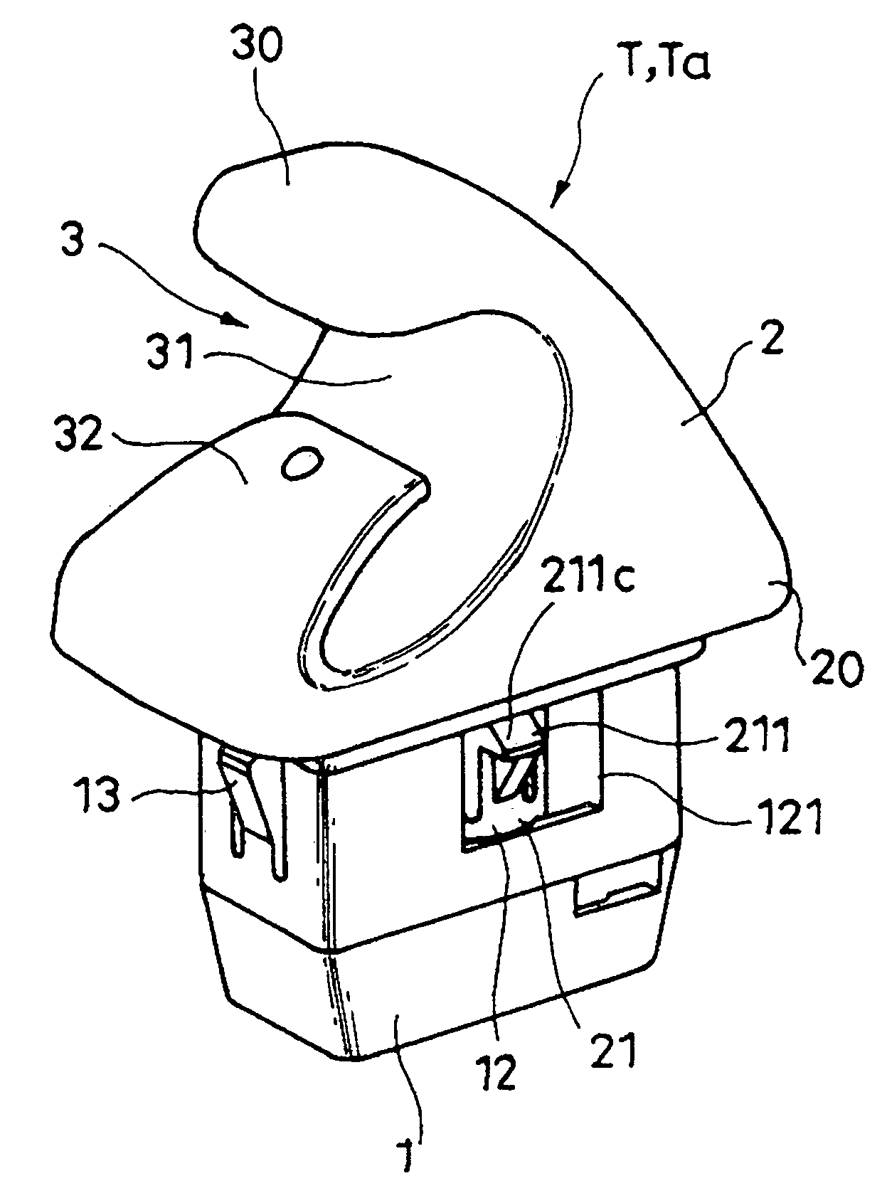
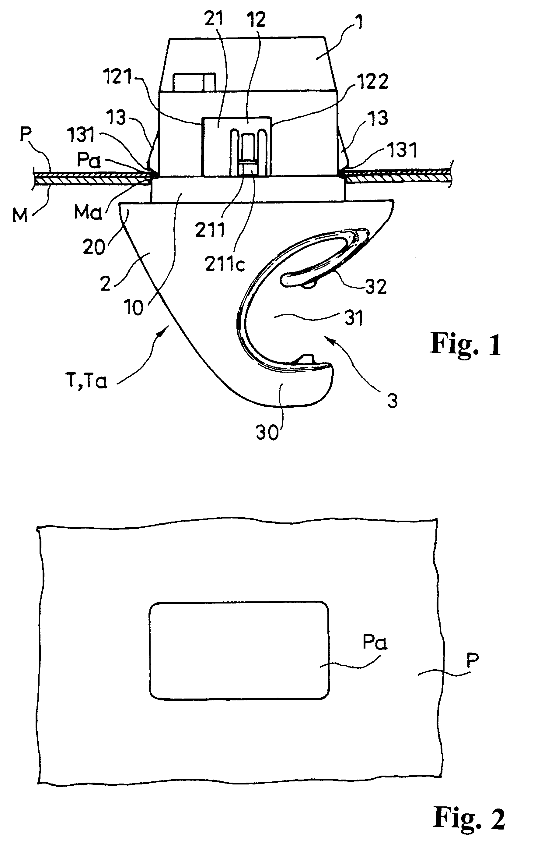
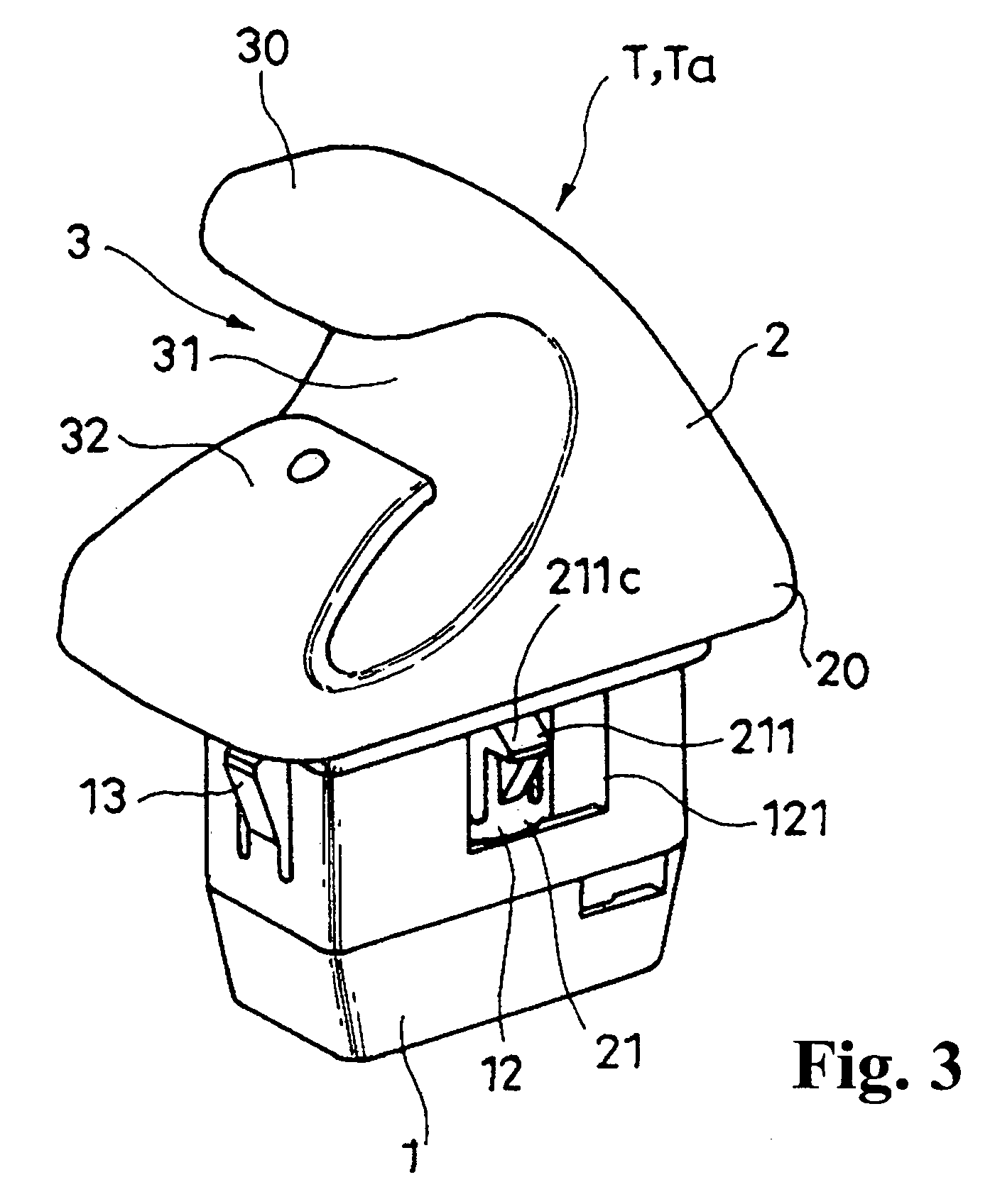
[0054]FIG. 1 and FIG. 3 through FIG. 11 respectively show a clamping tool Ta including an attached body T pertaining to the embodiment, and in particular, FIG. 1 shows the condition of use in which such clamping tool Ta is attached to a panel hole Pa, also, FIG. 5 shows the state in which the male part 2 was started to rotate toward the uncoupled position from the state in which the male part 2 is in the coupled position in FIG. 4. Also, FIG. 12 through FIG. 19 show the male part 2, and FIG. 20 through FIG. 26 show the female part 1. Also, FIG. 27 shows the condition of use of such clamping tool Ta when it is used as a sun visor clip for holding a shaft Sa of a sun visor S.

[0055]The attached body or member T to panel hole Pa pertaining to this embodiment is used for attaching to a panel such as a body panel P of an automobile by being fitted into a panel hole Pa prov...


PUM


Abstract

An attachment device to a panel hole includes a female part fitted into the panel hole, and having a pass-through part on a side thereof, and a male part having a leg part inserted into the female part. The leg part has an elastic coupling claw projecting outward from the pass-through part to be coupled in the panel hole, and a turn lock part. A guide member is formed in the female part for guiding rotation of the male part. The male part is assembled with the female part to be capable of rotation from a coupled position to an uncoupled position. A turn lock receiving part is formed in the female part and has a lock receiving surface for impeding rotation of the male part toward the uncoupled position.

Description

BACKGROUND OF THE INVENTION AND RELATED ART STATEMENT[0001]The invention relates to an improvement of an attaching member to be attached to a panel such as a body panel of an automobile by being fitted into a panel hole piercing through this panel, as well as a clamping tool constituted to include such attached body.[0002]There is a sun visor holder, which is constituted by a grommet member inserted into an interior material attachment hole and coupled to the interior material by a holding piece, and a holder member which is inserted into this grommet member to be capable of rotation and has a coupling claw projecting outward from a space formed on the side of this grommet member and couples to a panel attachment hole. (See Patent Document 1)[0003]However, in such sun visor holder, the panel attachment hole is coupled into by only the coupling claw of the holder member, and the grommet member itself is not coupled to the body panel.[0004]Also, in such sun visor holder, it is made su...

Claims


Application Information

Patent Timeline
Patent Type & Authority Patents(United States)
IPC IPC(8): H01R11/20
CPCF16B5/0642Y10T24/45099F16B2005/0671F16B21/02
Inventor HAMAGUCHI, TSUYOSHI
Owner NIFCO INC
Why Eureka
Try Eureka