Adsorptive separation of gas streams

a gas stream and separation technology, applied in the field of adsorptive separation, can solve the problems of limited overall achievable efficiency of the adsorptive separation system, and achieve the effect of greater adsorptive capacity

Active Publication Date: 2007-03-13
AIR PROD & CHEM INC
View PDF209 Cites 62 Cited by
  • Summary
  • Abstract
  • Description
  • Claims
  • Application Information

AI Technical Summary

Problems solved by technology

In all cases, the overall achievable efficiency of the adsorptive separation system is limited by the quantity and cost (in terms of external gas and heat energy or lost product gas) of purge gas required to desorb the contaminant from the adsorbent material during regeneration.

Method used


Image

  • Adsorptive separation of gas streams
  • Adsorptive separation of gas streams

Examples


Embodiment Construction

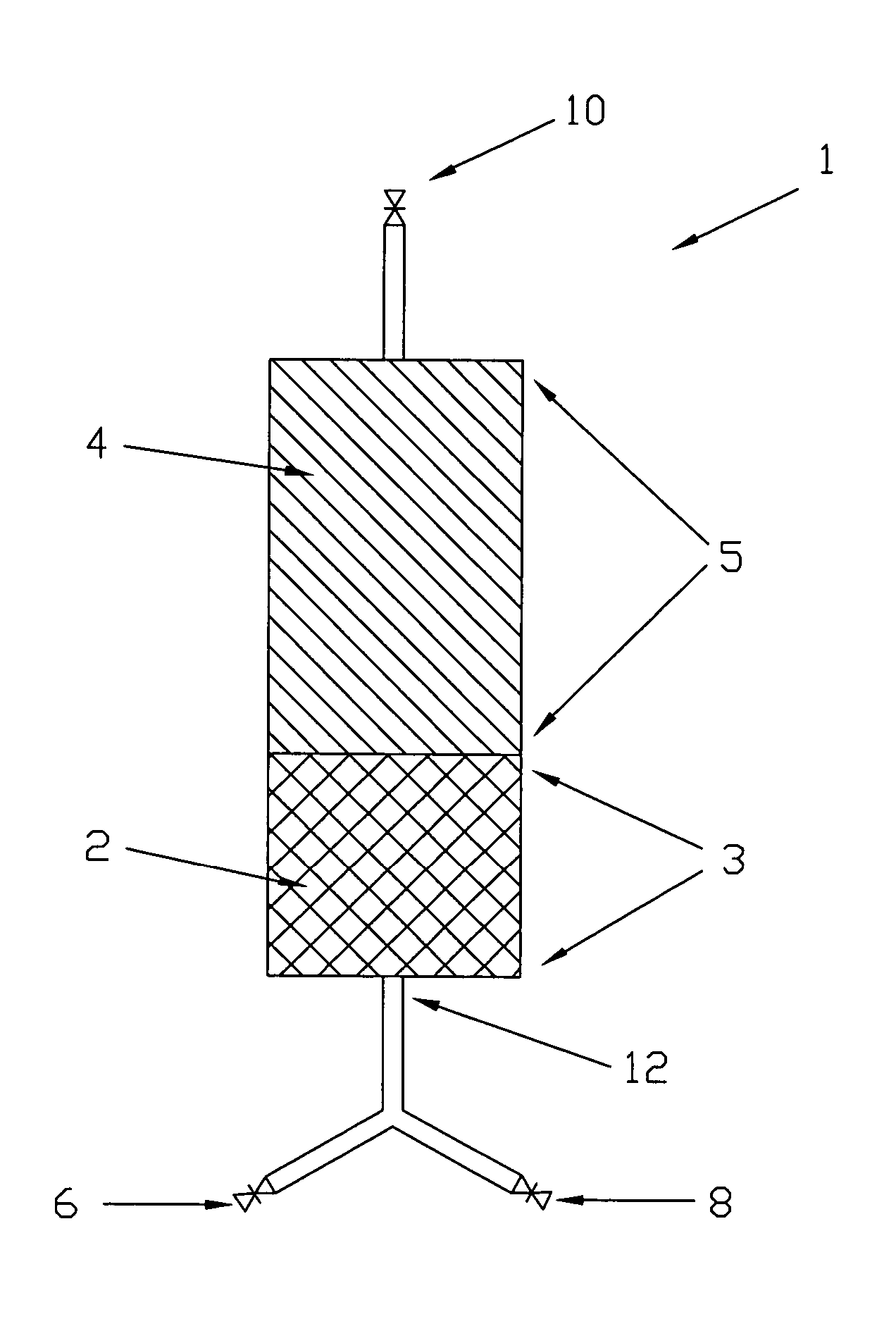
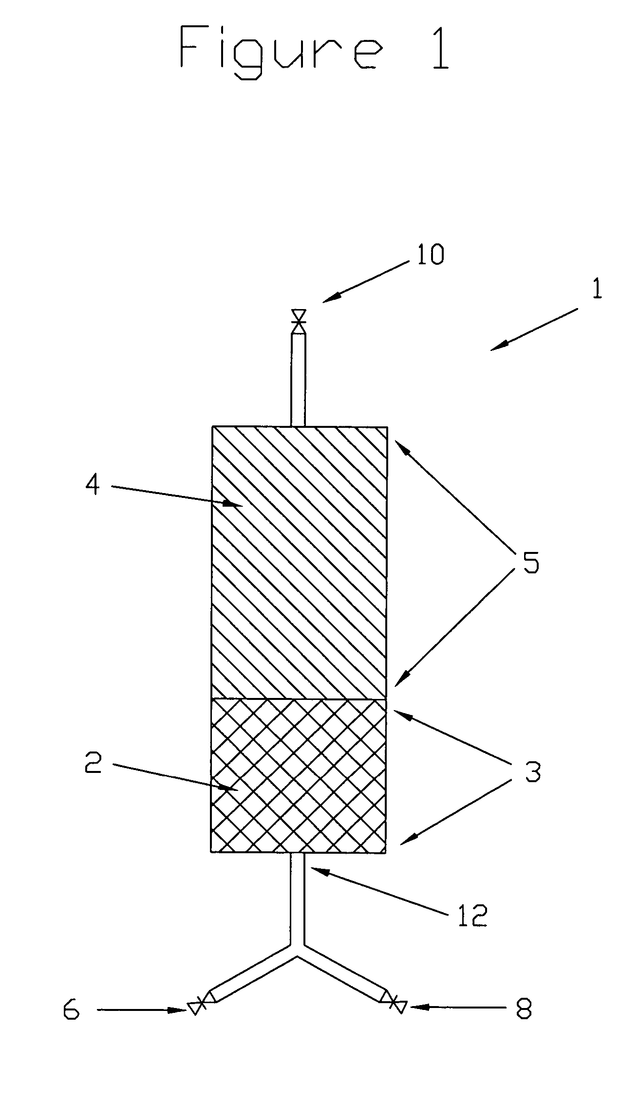
[0023]Disclosed herein are methods and systems for substantially separating a contaminant gas component from a feed gas stream comprising at least the contaminant gas component, a diluent gas component and a desired gas component, by means of adsorptive separation. The method and associated system utilize at least a first and second adsorbent materials, contained in at least first and second adsorption zones respectively, which may be typically enclosed inside at least one adsorption bed. The first and second adsorbent materials may be compositionally distinct from each other, and may be selected based on their adsorption characteristics relative to the contaminant, diluent and desired product gas components of the feed gas stream for a desired adsorptive separation application. The first adsorbent material is chosen such that it is adsorptively selective for the contaminant component, relative to the diluent component, so that when the feed gas is passed through the first adsorptio...


PUM


Abstract

A method and system for adsorptive separation of a feed gas mixture provides for increased system efficiency and product recovery. The requirement for purge gas streams consuming desired product gas to regenerate adsorption beds is reduced through an inventive method for adsorbent selection and adsorption bed and process design.

Description

FIELD[0001]The present disclosure relates to adsorptive separation, and more particularly to an improved method and apparatus for adsorptive separation of gas streams.BACKGROUND[0002]Adsorptive processes are an established means of separation used to separate gas phase components in multicomponent gas streams found in many industrial applications. Many industrial gas streams contain contaminant components which may be advantageously separated from the gas stream prior to some downstream use. Adsorptive separation processes have been adapted for use in many such industrial applications.[0003]Thermal and pressure swing adsorption processes (TSA and PSA) as known in the prior art have both been successfully adapted to remove contaminant components from commercially important gas streams, making use of specialized adsorbent materials to adsorb contaminants from the input, or feed gas stream, leaving the desired product gas stream substantially free of the contaminants. Such adsorbent ma...

Claims


Application Information

Patent Timeline
Patent Type & Authority Patents(United States)
IPC IPC(8): B01D53/04B01D53/02
CPCB01D53/0423B01D53/0446B01D2256/16Y02E50/346B01D2257/502B01D2259/40086B01D2259/4146B01D2256/24Y02E50/30
Inventor ALIZADEH-KHIAVI, SOHEILROY, SURAJITSAWADA, JAMES A.
Owner AIR PROD & CHEM INC
Why Eureka
Try Eureka