Carbon Dioxide Recovery

a carbon dioxide and recovery technology, applied in the field of carbon dioxide recovery, can solve the problems of affecting the climatic conditions, unable to achieve the reduction of greenhouse gas emissions required to stabilize the greenhouse gas level, and inability to reduce the emission of greenhouse gases

Active Publication Date: 2010-10-07
INNOSEPRA LLC
View PDF5 Cites 153 Cited by
  • Summary
  • Abstract
  • Description
  • Claims
  • Application Information

AI Technical Summary

Problems solved by technology
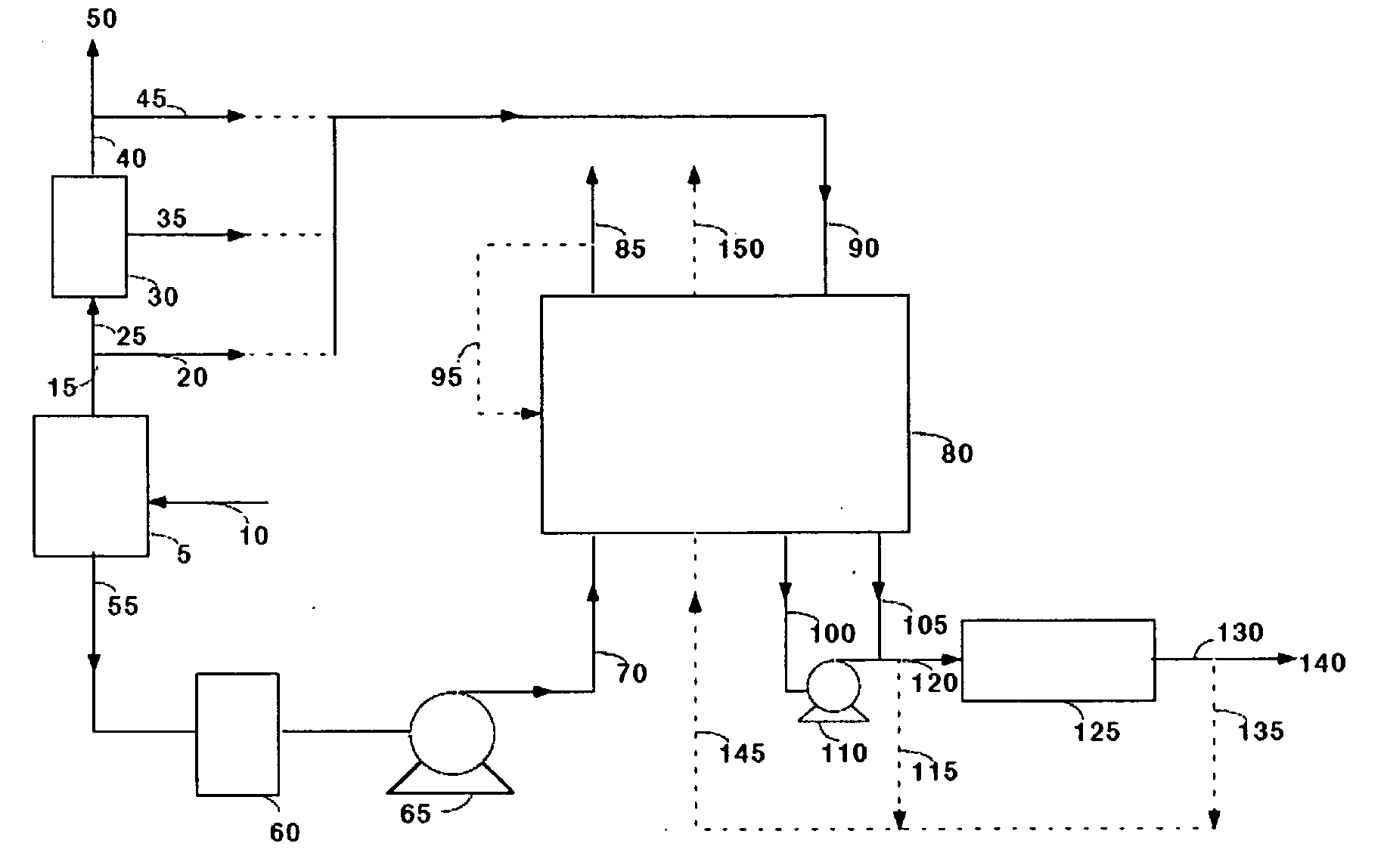
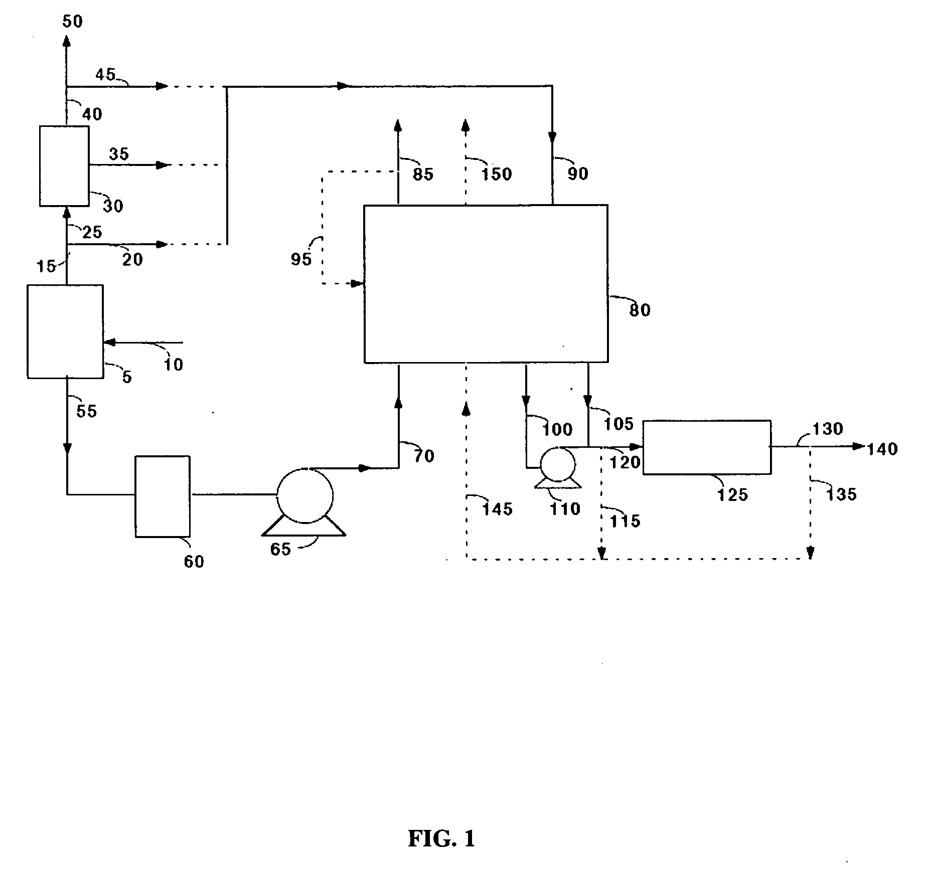
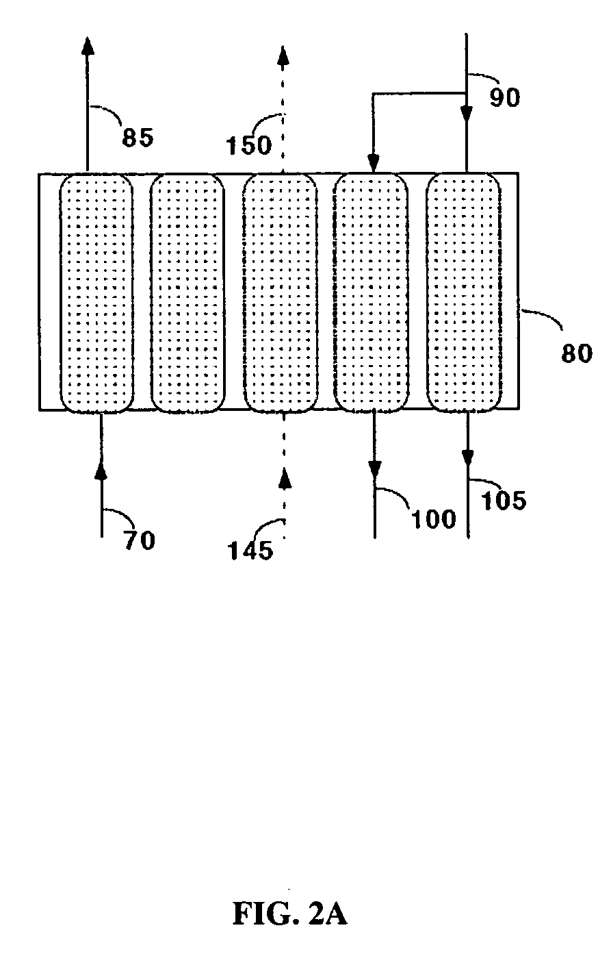
Emissions of greenhouse gases such as CO2, if left unchecked, may potentially affect climatic conditions.
Conversion of fossil fuels such as coal and natural gas to energy is a source of greenhouse gas emissions.
Emissions of the greenhouse gases can be reduced by various means such as increase in efficiency of the combustion process and use of renewable energy such as wind and solar but the reduction in the emission of the greenhouse gases required to stabilize the greenhouse gas levels cannot be achieved without capturing a substantial part of the greenhouse gases at the source of the greenhouse gas emissions during either the pre-combustion process or the post-combustion process.
The absorption-based processes have drawbacks such as the significant capital requirements.
Furthermore, amine-based processes require the use of specialty steel equipment and the associated capital investment because of the corrosive nature of amine and ammonia solutions in the presence of acidic gases and oxygen.
This equipment represents a significant capital cost.
These systems typically remove less than 2% of impurities and the regeneration outlet stream containing the impurities is not of high purity.
For example, assuming a working capacity of 12 weight % (difference in capacity between the adsorption and the regeneration steps), an adsorbent density of about 660 kgs / m3 and an adsorption time of 4 hours, a plant processing 1000 tons / day of CO2 in the feed would require about 8,000 m3 (5.3 million kilograms) of the adsorbent, a size that makes the systems not practical for capturing carbon dioxide from combustion sources.

Method used


Image

  • Carbon Dioxide Recovery
  • Carbon Dioxide Recovery
  • Carbon Dioxide Recovery

Examples


example 1

[0050]Commercially available 5A zeolite of 8×12 mesh size (about 1.5 mm) was obtained from Aldrich Corporation and loaded in two 18 mm diameter adsorbent beds. The total weight of adsorbent was about 500 grams (gms). A feed stream containing about 12.5% CO2 with the balance being nitrogen, to simulate flue gas from a coal-fired power plant, was passed through these beds at a flow rate of 11 standard liters / min and at a pressure of 1.34 bara. The standard conditions refer to 21.1° C. and 1 bara. The adsorbing bed was cooled with a jacket containing a water / glycol mixture at 30° C. The regenerating bed was heated with a jacket containing water / glycol mixture at 100° C. The concentrations in the CO2-depleted stream and in the CO2 product were analyzed using an infrared CO2 analyzer. The cycle for this process is shown in Table II. After heating, the beds were evacuated to a pressure of about 0.25 bara during the evacuation steps. For these process conditions, an average CO2 purity of 9...

example 2

[0051]The process of Example 1 was run at different adsorption temperatures. Other process conditions, namely the feed pressure, feed CO2 concentration, and the adsorbent material were the same as in Example 1. Again, the concentrations in the CO2-depleted stream and in the CO2 product stream were analyzed using an infrared CO2 analyzer. The process cycle of Table II was used. For a feed temperature of 20° C., an average CO2 purity of 99.0% and an average CO2 recovery of 88% were obtained. For a feed temperature of 40° C., an average CO2 purity of 99.2% and an average CO2 recovery of 84% were obtained.

example 3

[0052]The process of Example 1 was run with a commercially available 13X zeolite of 8×12 mesh size (1.5 mm) obtained from the Aldrich Corporation. The feed pressure, and the feed CO2 concentration were the same as in Example 1 and the process cycle of Table II was used. Again, the concentrations in the CO2-depleted stream and in the CO2 product stream were analyzed using an infrared CO2 analyzer. For a feed temperature of 20° C., an average CO2 purity of 98.5% and an average CO2 recovery of 87% were obtained. For a feed temperature of 30° C., an average CO2 purity of 98.5% and an average CO2 recovery of 78% were obtained.


PUM


Abstract

Disclosed herein is a method and system for separating carbon dioxide (CO2) from a CO2 containing gas stream containing water vapor and additional impurities, for example, nitrogen, oxygen, sulfur oxides, nitrogen oxides, and mercury. The CO2 is captured by subjecting the CO2 gas feed stream to a temperature swing adsorption step. The temperature swing adsorption step comprises an adsorption step for producing a substantially dry carbon dioxide-depleted stream, and an adsorbent regeneration step comprising heating the adsorbent bed to produce a substantially water vapor-free carbon dioxide stream. Moisture from the gas stream containing CO2 is optionally removed by pressure swing adsorption, temperature swing adsorption, membrane separation, or absorption prior to CO2 capture.

Description

CROSS REFERENCE TO RELATED APPLICATIONS[0001]This application claims the benefit of provisional patent application No. 61 / 123,259 titled “Process For Carbon Dioxide Recovery”, filed on Apr. 7, 2008 in the United States Patent and Trademark Office.BACKGROUND[0002]The method and system disclosed herein relates to capturing carbon dioxide (CO2) from combustion sources such as flue gas of a power plant and making the CO2 available for sequestration or other uses.[0003]Emissions of greenhouse gases such as CO2, if left unchecked, may potentially affect climatic conditions. Conversion of fossil fuels such as coal and natural gas to energy is a source of greenhouse gas emissions. Emissions of the greenhouse gases can be reduced by various means such as increase in efficiency of the combustion process and use of renewable energy such as wind and solar but the reduction in the emission of the greenhouse gases required to stabilize the greenhouse gas levels cannot be achieved without capturin...

Claims


Application Information

Patent Timeline
Patent Type & Authority Applications(United States)
IPC IPC(8): B01D53/047B01D53/22B01D53/02B01D53/14
CPCB01D53/0462B01D53/047B01D2257/30B01D2257/404Y02C10/10B01D2257/602B01D2257/80Y02C10/06Y02C10/08B01D2257/504Y02C20/40
Inventor JAIN, RAVI
Owner INNOSEPRA LLC
Why Eureka
Try Eureka