Exhaust treatment device

Active Publication Date: 2007-03-13
UMICORE AG & CO KG
View PDF28 Cites 37 Cited by
  • Summary
  • Abstract
  • Description
  • Claims
  • Application Information

AI Technical Summary

Benefits of technology

[0016]In another embodiment, the exhaust treatment device comprises a first block in fluid communication with a second block, the first block comprising a plurality of filter elements and plugs alternately arranged in a serpentine-like structure to form a plurality of inlet channels and outlet channels, wherein the plugs are disposed at alternating ends of the filter elements, and wherein fluid communication from the inlet channels to the outlet channels is through the filter elements, a soot oxidation catalyst composition formed from an inorganic precursor and a catalytic metal disposed on or impregnated in surfaces that form the inlet channels, an

Problems solved by technology

However, NOX adsorber catalysts are sensitive to sulfur poisoning and must be periodically desulfurized, otherwise their performance gradually decreases.
If the catalytic element and particulate filter (or catalytic particulate filter) are separate elements, they require a large installation space in the exhaust line, which is usually not

Method used


Image

  • Exhaust treatment device
  • Exhaust treatment device
  • Exhaust treatment device

Examples


Embodiment Construction

[0019]Disclosed herein is an exhaust treatment device that combines the functionalities of a catalytic particulate filter and a NOx absorber catalyst into a single integral device for use downstream from an engine, e.g., preferably manifold mounted or close coupled. As will be described in further detail, the exhaust treatment device effectively removes particulate soot and reduces concentration of NOx as well as optionally reducing the concentration of unburned hydrocarbons, carbon monoxide, and other undesirable exhaust gas components, from exhaust gases flowing through the exhaust conduit.

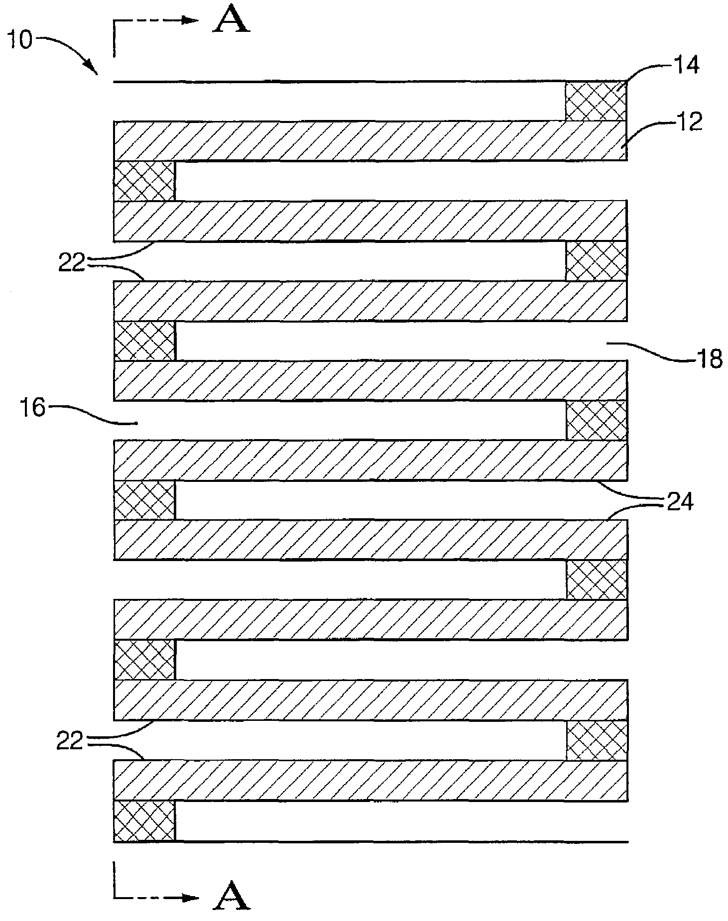
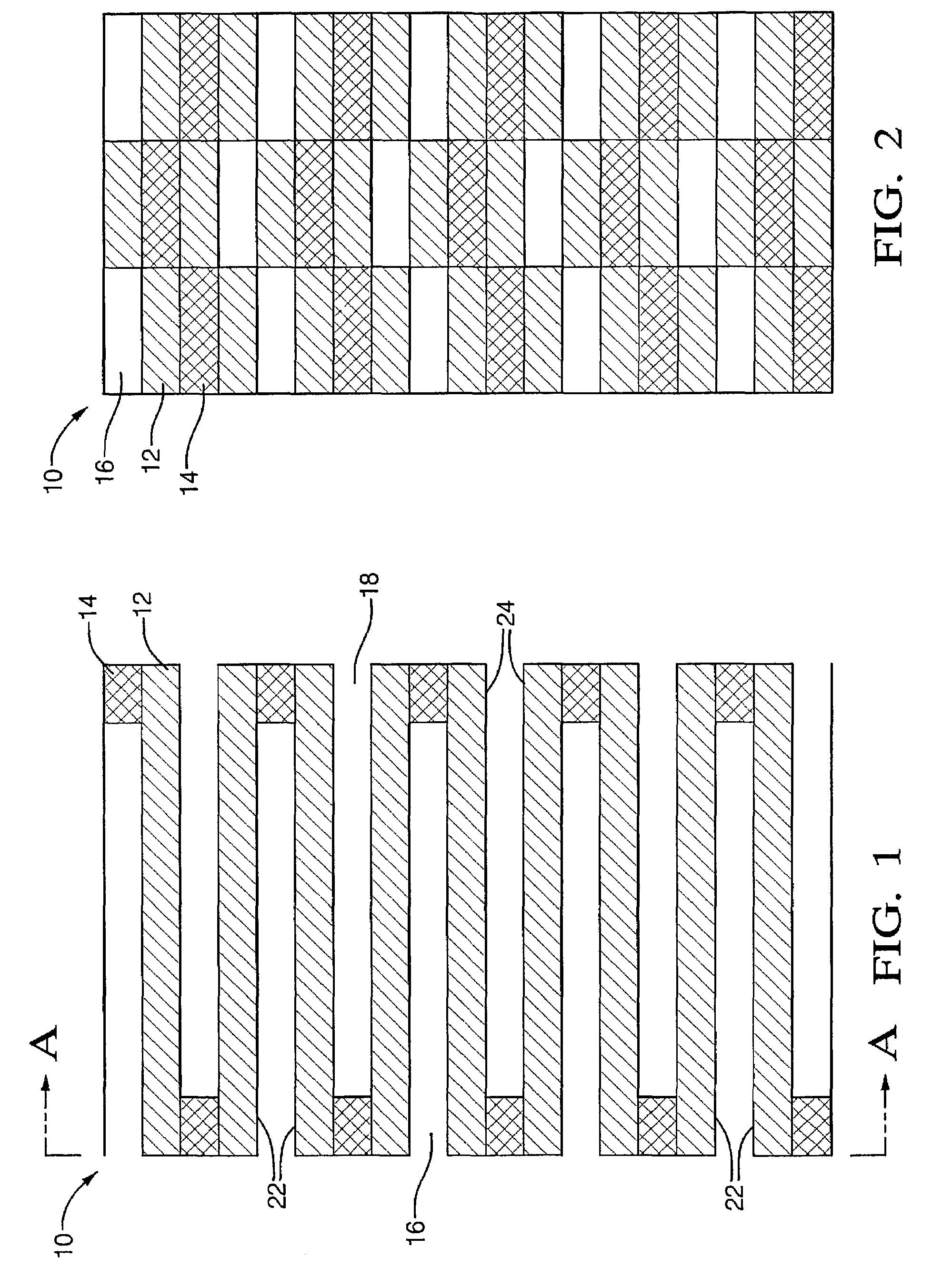
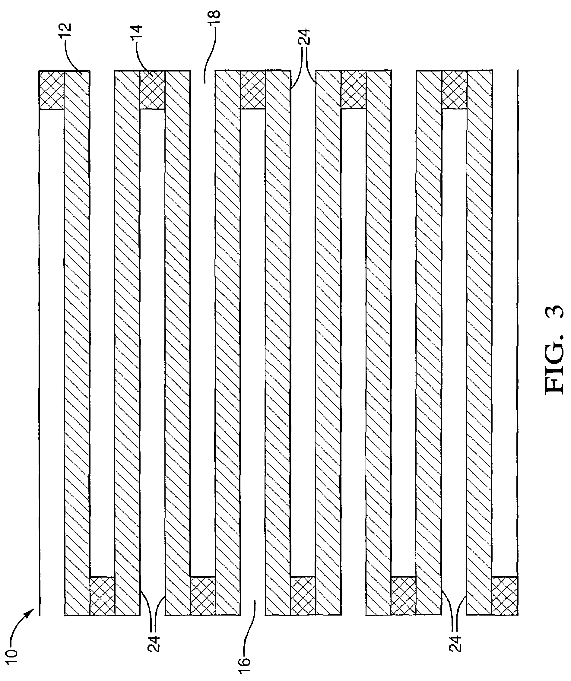
[0020]FIGS. 1 and 2 illustrate one embodiment of an exhaust treatment device 10 that generally comprises a plurality of porous filter elements 12. Plugs 14 are interposed at and between alternating ends of the filter elements 12 to form inlet channels 16 and outlet channels 18, i.e., a serpentine-like cross sectional structure as shown. Preferably, the filter elements 12 are planar and equally s...


PUM

PropertyMeasurementUnit
Temperatureaaaaaaaaaa
Weightaaaaaaaaaa
Thicknessaaaaaaaaaa

Abstract

An exhaust treatment device for treating an exhaust gas stream combines the functionalities of a catalytic particulate filter and a NOx absorber catalyst into a single integral device and is disposed in an exhaust conduit. By combining the functionalities of the catalytic particulate filter and a NOx absorber catalyst into a single integral device, the exhaust treatment device eliminates the temperature losses inherent to the heat capacity of one catalytic device placed in front of the other.

Description

FIELD OF THE INVENTION[0001]The present disclosure relates to NOx and particle abatement, particularly with NOx and particle abatement in exhaust gas streams discharged from automotive engines.BACKGROUND[0002]In order to meet government mandated exhaust gas emission standards, the exhaust gases of an automotive internal combustion engine must be treated before emission into the atmosphere. Exhaust gas streams are typically passed through a device containing a catalytic element to remove undesirable gaseous emission components such as unburned hydrocarbons, carbon monoxide and nitrogen oxides. The removal of NOX components is of particular concern, and can be accomplished using a device employing elements containing a NOX adsorber catalyst. However, NOX adsorber catalysts are sensitive to sulfur poisoning and must be periodically desulfurized, otherwise their performance gradually decreases.[0003]In addition to the gaseous components, exhaust gas streams also contain particulate matt...

Claims


Application Information

Patent Timeline
IPC IPC(8): B01D50/00B32B27/02B01D53/94F01N3/022F01N3/023F01N3/035F01N3/08F01N13/02
CPCB01D53/944F01N13/0097F01N3/0231F01N3/035F01N3/0821F01N3/0842B01D2255/102B01D2255/202B01D2255/204B01D2255/91Y10S55/30F01N3/0222
Inventor MOLINIER, MICHELBAILEY, OWEN H.
Owner UMICORE AG & CO KG
Why Eureka
Try Eureka