Seat occupant load sensor
a technology for occupant load sensors and seats, applied in the direction of instruments, force/torque/work measurement apparatus, tractors, etc., can solve the problems of seat falling off, occupant load sensor broken, complex structure, etc., to accurately measure the load, accurately detect the load, and accurately detect the load
- Summary
- Abstract
- Description
- Claims
- Application Information
AI Technical Summary
Benefits of technology
Problems solved by technology
Method used
Image
Examples
first embodiment
[Modified Example of First Embodiment]
[0101]FIG. 8 shows an occupant load sensor 10 in accordance with a modified example of the first embodiment, and FIG. 9 shows a state in which the occupant load sensor 10 is attached to the seat rail. FIG. 9B is a side elevational view of the seat rail 40, and FIG. 9A is a cross sectional view along a line A4—A4 in FIG. 9B. FIG. 8A is an explanatory view of an attachment of the occupant load sensor, and FIG. 8B is a cross sectional view along a line B2—B2 in FIG. 9A.
[0102]The occupant load sensor in accordance with the first embodiment is fixed by the bolt 69. On the contrary, the occupant load sensor in accordance with the modified example of the first embodiment is fixed by a shoulder bolt 68 and a bolt 69.
[0103]As shown in FIG. 8B, the occupant load sensor 10 is constituted by a flange portion 20 which is in surface contact with a lower surface of the lower rail (the seat side fixing member) 44 and is attached by the shoulder bolt 68 and the ...
second embodiment
[Modified Example of Second Embodiment]
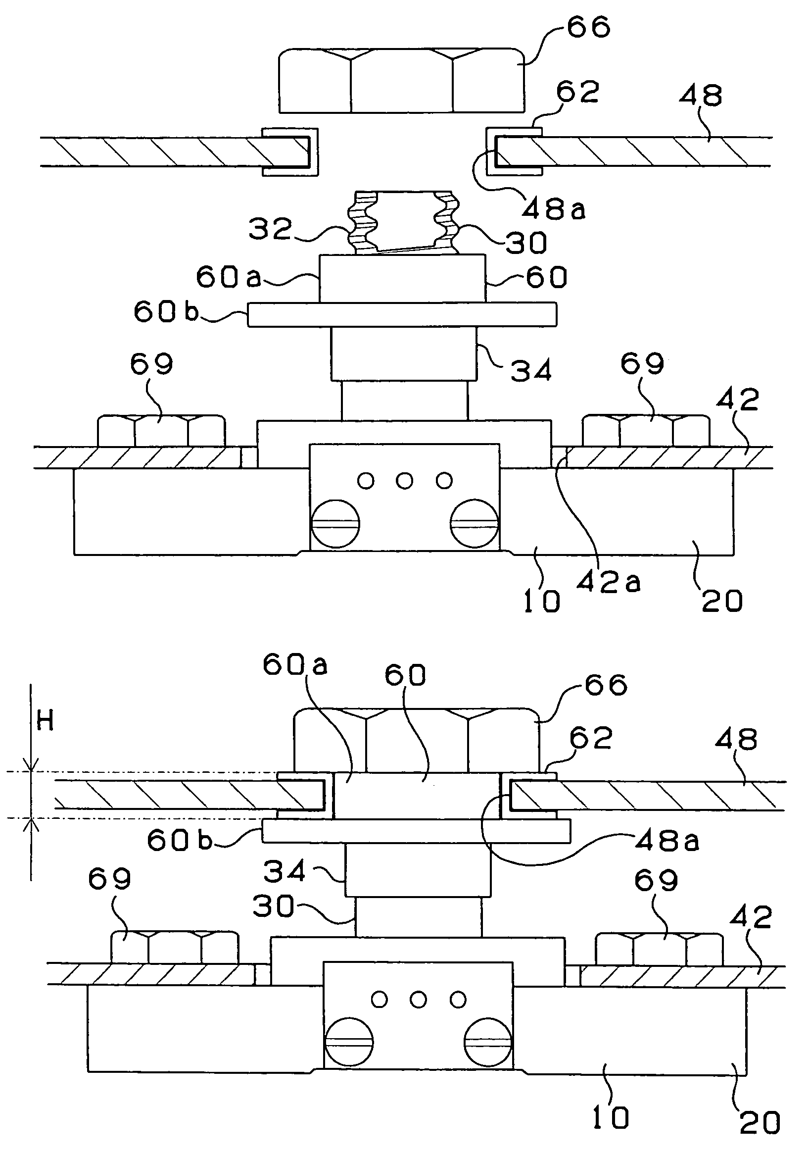
[0113]FIG. 12B is a side elevational view showing a state in which an occupant load sensor in accordance with a modified example of the second embodiment is attached to the seat rail, and FIG. 12A is a cross sectional view along a line A6—A6 in FIG. 12B. The occupant load sensor in accordance with the second embodiment is fixed to the seat rail by the bolt 69. On the contrary, the occupant load sensor in accordance with the modified example of the second embodiment is fixed to the seat rail by the shoulder bolt 68 and the bolt 69. In the modified example of the second embodiment, the occupant load sensor 10 is arranged between the upper rail 42 of the seat rail 40 and the bracket 48 fixing the seat. FIG. 13A is a side elevational view showing a state before the occupant load sensor in accordance with the modified example of the second embodiment is attached to the seat rail, and FIG. 13B is a side elevational view showing a state after being at...
third embodiment
[Third Embodiment]
[0114]A description will be given of an occupant load sensor in accordance with a third embodiment of the present invention with reference to FIG. 14. FIGS. 14A and 14B are explanatory views showing an attached position of the occupant load sensor with respect to the seat in accordance with the first embodiment, and FIG. 14C is an explanatory view showing the occupant load sensor in accordance with the third embodiment.
[0115]In the occupant load sensor 10 in accordance with the first embodiment, as shown in FIG. 14B, in the case that the attached position of a pair of seat rails 40 is largely deflected, the occupant load sensor 10 is attached in a state in which the force in the other directions than the vertical direction is applied, so that it is hard to accurately detect the load. On the contrary, the occupant load sensor 10 in accordance with the third embodiment is structured such that a pair of seat rails 40 are connected via a connection bracket 52, thereby ...
PUM
 Abstract
Description
Claims
Application Information
 - R&D
- Intellectual Property
- Life Sciences
- Materials
- Tech Scout
- Unparalleled Data Quality
- Higher Quality Content
- 60% Fewer Hallucinations
Browse by: Latest US Patents, China's latest patents, Technical Efficacy Thesaurus, Application Domain, Technology Topic, Popular Technical Reports.
© 2025 PatSnap. All rights reserved.Legal|Privacy policy|Modern Slavery Act Transparency Statement|Sitemap|About US| Contact US: help@patsnap.com


