
Network optimisation method

a network optimization and network technology, applied in the field of packet-based communication networks, can solve problems such as insufficient, links on the shortest path between certain ingress-egress pairs may get congested, and not always make good use of available network resources

Active Publication Date: 2007-03-13
NETABOCKET
View PDF4 Cites 26 Cited by
  • Summary
  • Abstract
  • Description
  • Claims
  • Application Information

AI Technical Summary

Benefits of technology

[0051]Deployment. Network operators all over the world are using different solutions for their networks. For any type of global service, support for heterogeneous networking technologies is very important. This invention makes it possible to deploy bandwidth guaranteed end-to-end VLL services across the two of the most commonly used QoS models.

Problems solved by technology

Some of the major issues are: (1) extending the service model, (2) routing and forwarding efficiency and scalability, and (3) operations and management.
While this shortest path routing is sufficient to achieve connectivity, it does not always make good use of available network resources and is not satisfactory from a traffic-engineering point of view.
A prime problem is that some links on the shortest path between certain ingress-egress pairs may get congested while links on possible alternate paths remain free.
Even in the best effort model, this means that available network resources are not being used well, resulting in higher delays, and there is a potential for providing better quality of service (QoS) with the same network infrastructure.
However, this model does not allow for quality guarantees, without additional functionality for service differentiation in network devices.
While solving the scalability issues, DiffServ fails to provide adequate guidance with regard to implementation of an admission control policy.
A service that is only available within one provider domain is unlikely to be successful in a world where global services of all kinds are increasingly important.
Planning resources over time is an important issue if bandwidth guaranteed services on otherwise shared networks are to become a credible alternative to more rigid solutions such as leased lines or circuit switched networks.
A business whose mission critical applications fail due to unavailability of network QoS is very likely to abandon the failing provider.
The inability to plan over time requires a compromise in network utilisation versus customer values.
For MPLS networks, there is currently no known solution to this problem.
However, this paper does not disclose a method for performing the resource reservations in a network having heterogeneous MPLS domains.

Method used


Image

  • Network optimisation method
  • Network optimisation method
  • Network optimisation method

Examples


Embodiment Construction

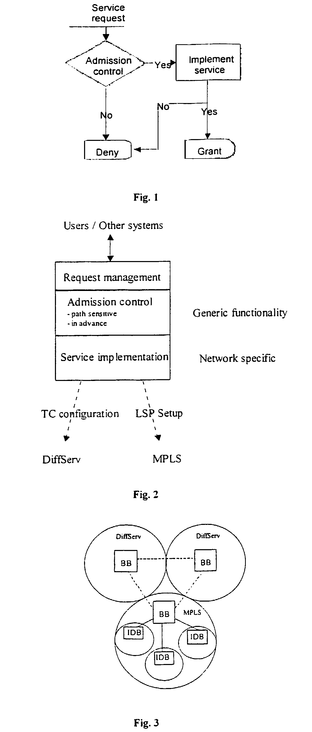
[0059]FIG. 2 shows functional blocks that schematically illustrate the present invention.

[0060]Note that the routing part of [RATES] is excluded and that the method according to the present invention relies entirely on existing routing and does not itself actively compute routes.

[0061]By referring to FIG. 2 the functionality of the present invention is schematically described below:[0062]Request management. This interface handles all incoming requests. Requests are made either by clients to the system (within the system's domain) or peering systems in other domains. This functionality of this interface can be either that of [RATES] or [OLOV] or both.[0063]Admission control. This block is implemented e.g. as described in [OLOV] to achieve path sensitivity and the ability to plan ahead of time. The same functionality is used for MPLS and DiffServ. The key components of this block are:[0064]Topology information, which is used to compute paths for the requests (path sensitivity).[0065]A...


PUM


Abstract

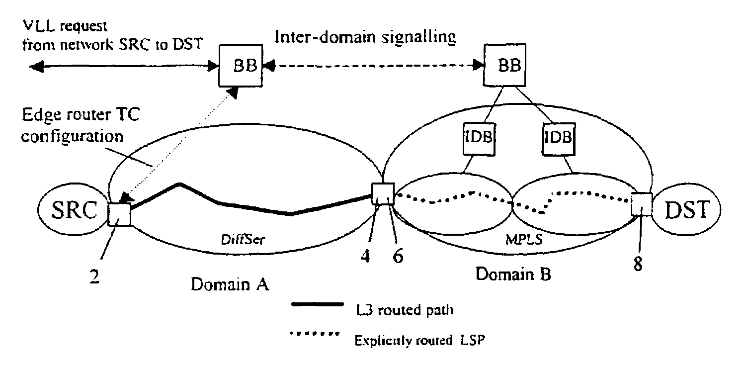
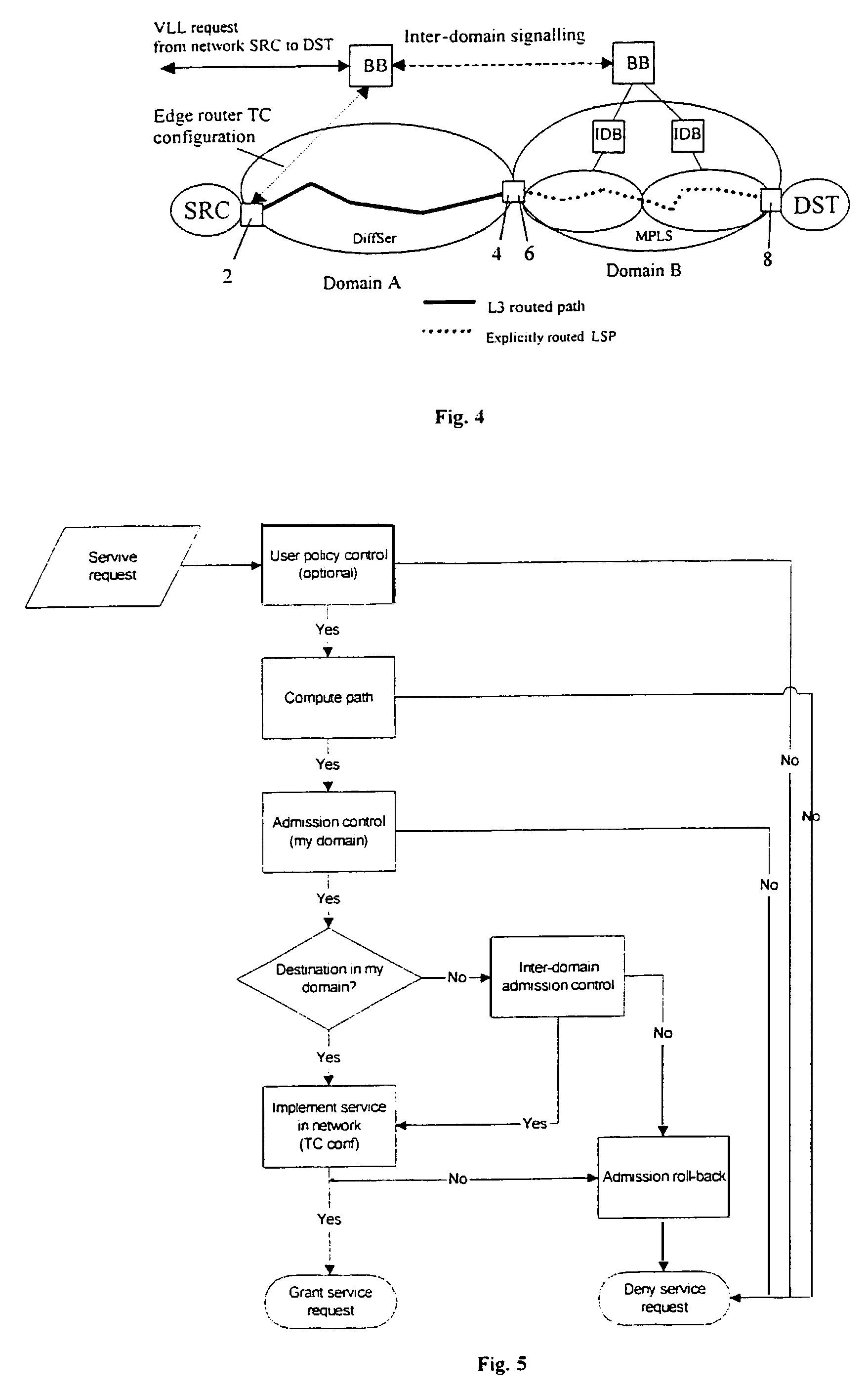
Method in a packet based communication network including network domains to establish a virtual leased line (VLL) between a source (SRC) and a destination (DST) in different domains in order to achieve packet transfer between the source and the destination, wherein a bandwidth broker (BB) is associated to each network domain.

Description

FIELD OF THE INVENTION[0001]The present invention relates to a method in a packet based communication network including network domains to establish a virtual leased line (VLL) between a source (SRC) and a destination (DST) in different domains in order to achieve packet transfer between the source and the destinationBACKGROUND OF THE INVENTION[0002]Within the Internet community there are several initiatives towards improving different aspects of the Internet. Some of the major issues are: (1) extending the service model, (2) routing and forwarding efficiency and scalability, and (3) operations and management.[0003]All of these are important to the continued growth and success of the Internet. The present application is related to a combination of two emerging technologies, MultiProtocol Label Switching (MPLS) and Bandwidth Brokers (BB), which have great potential in the context of all three mentioned issues. The main focus of the present invention is on the implementation of a band...

Claims


Application Information

Patent Timeline
Patent Type & Authority Patents(United States)
IPC IPC(8): H04L12/28H04L12/56H04L12/24H04L12/46
CPCH04L12/4633H04L47/829H04L41/0896H04L41/5003H04L45/02H04L45/302H04L45/306H04L45/308H04L45/50H04L47/10H04L47/15H04L47/22H04L47/2408H04L47/2425H04L47/781H04L47/785H04L47/805H04L47/825H04L12/5695H04L41/5067H04L41/0897H04L47/83H04L12/28H04L47/70
Inventor SVANBERG, EMILJOHANSSON, JOACHIMTORGER, ANDERSNORRGARD, JOAKIMLARSSON, ANDERS
Owner NETABOCKET
Learn More