Motion control apparatus for vehicle

a technology of motion control apparatus and vehicle, which is applied in the direction of brake systems, instruments, machines/engines, etc., can solve problems such as difficulty in coping

Inactive Publication Date: 2007-03-13
HONDA MOTOR CO LTD
View PDF9 Cites 8 Cited by
  • Summary
  • Abstract
  • Description
  • Claims
  • Application Information

AI Technical Summary

Benefits of technology

[0010]According to the construction of the second feature, the motion state of the vehicle is determined based on the difference between the radius of the corner on which the own vehicle is traveling and the actual turning radius being the turning radius of the traveling locus which the own vehicle will draw when entering the corner, to determine at least whether the motion state of the own vehicle is in the understeer state or the oversteer state. Therefore, by performing the motion control of the vehicle based on the determination result, the vehicle can be made to travel to pass the corner reliably even when the steering is turned excessively, or deceleration is insufficient.

Problems solved by technology

However, in the control for the vehicle to pass a corner easily by deceleration of the vehicle speed as in the above-described prior art, it is difficult to cope with such a situation as the driver excessively turns steering (hereinafter referred to as an operation which gives excessive steering input force exceeding the maximum lateral acceleration possible to occur with respect to the friction coefficient of the road surface on which the vehicle is traveling), and as the driver cannot decelerate to the speed at which the vehicle easily passes the corner.

Method used


Image

  • Motion control apparatus for vehicle
  • Motion control apparatus for vehicle
  • Motion control apparatus for vehicle

Examples


Embodiment Construction

[0018]The present invention will be explained below based on one embodiment of the present invention shown in the attached drawings.

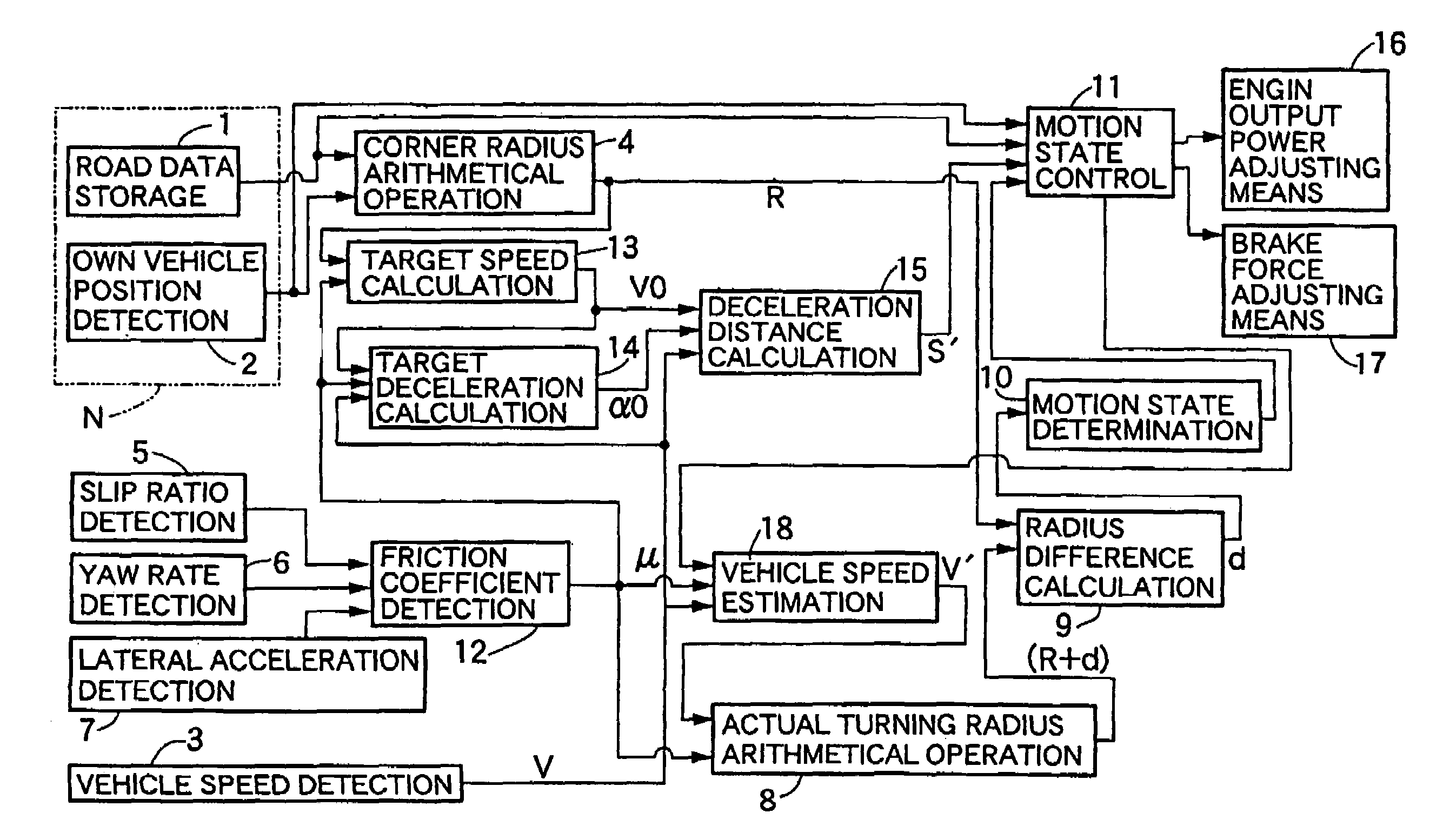
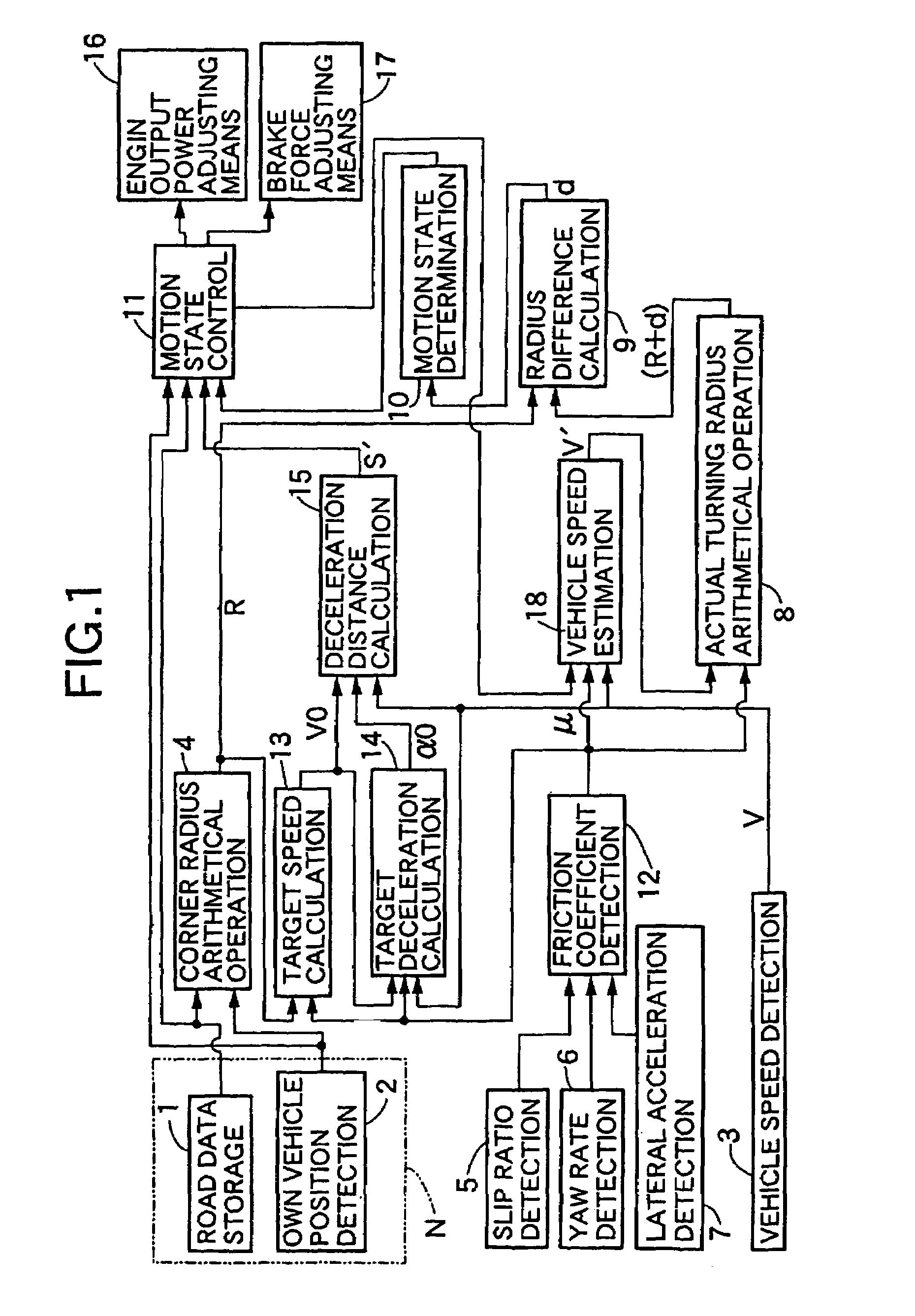
[0019]First, in FIG. 1, a motion control apparatus of a vehicle includes road data storing means 1 for storing road data, own vehicle position detecting means 2 for detecting an own vehicle position on the road data, vehicle speed detecting means 3 for detecting an own vehicle speed, a corner radius arithmetically operating means 4 for obtaining a radius of a corner existing on a route on which the own vehicle is traveling at present, based on the road data and the own vehicle position, slip ratio detecting means 5, yaw rate detecting means 6 and lateral acceleration detecting means 7 as first to third motion parameter detecting means for respectively detecting a slip ratio, a raw rate and lateral acceleration being motion parameters showing a turning motion state of the own vehicle, actual turning radius arithmetically operating means 8 for arithmetica...


PUM


Abstract

A radius of a corner is determined by using a corner radius calculating device based on road data and data related to position of a vehicle on the road. An actual turning radius when the vehicle enters the corner is estimated by an actual turning radius calculating device based on at least a vehicle speed and motion parameters of the vehicle, and the motion state of the vehicle is controlled by the motion state control device so that an actual turning radius of the vehicle becomes close to the radius of the corner based on a calculation by radius difference calculating device for calculating a difference between the calculated corner radius and the actual turning radius. Thus, a motion state of the vehicle at a time of traveling around the corner is properly controlled to enable the vehicle to pass the corner reliably.

Description

BACKGROUND OF THE INVENTION[0001]1. Field of the Invention[0002]The present invention relates to a motion state control apparatus for controlling a motion state of a vehicle so as to pass a corner of a road properly by utilizing a so-called navigation system including road data storing means for storing road data, and an own vehicle position detecting means for detecting an own vehicle position on the road data.[0003]2. Description of the Related Art[0004]A motion control apparatus for a vehicle for controlling a vehicle speed so that the own vehicle properly passes a corner existing ahead of the own vehicle by utilizing a navigation system is already known (see Japanese Patent No. 3062777).[0005]However, in the control for the vehicle to pass a corner easily by deceleration of the vehicle speed as in the above-described prior art, it is difficult to cope with such a situation as the driver excessively turns steering (hereinafter referred to as an operation which gives excessive ste...

Claims


Application Information

Patent Timeline
Patent Type & Authority Patents(United States)
IPC IPC(8): G06F19/00B60W10/04B60T7/12B60T8/1755B60T8/58B60W10/06B60W10/18B60W10/184B60W30/00B60W30/02B60W30/045F02D29/02G05D1/02
CPCB60T8/1755B60W10/06B60W30/045B60W40/06B60W10/18B60T2210/24B60T2210/36Y02T10/84B60W2550/143B60W2550/402B60W2552/20B60W2552/30B60W2556/50
Inventor KIN, KEIYU
Owner HONDA MOTOR CO LTD
Why Eureka
Try Eureka