Method for multiple sensors to communicate on a uni-directional bus

a communication method and sensor technology, applied in the field of communication systems, can solve the problems of increasing the cost of adding a transmitting sensor to the system, the cost of the additional transmitting sensor and the interface of the sensor, and the significant increase in the initial cost within the rcu b>308/b>, and the incremental cost of adding a sensor to the system b>300/b> is limited to the cost of the additional sensor

Active Publication Date: 2007-03-13
APTIV TECH LTD
View PDF22 Cites 10 Cited by
  • Summary
  • Abstract
  • Description
  • Claims
  • Application Information

AI Technical Summary

Benefits of technology

[0009]The present invention provides a data communication system that avoids some of the costs necessarily incurred with the implementation of the prior art systems, i.e., the costs of obtaining transmitting sensors with bi-directional communication capability, RCUs that support bi-directional communication capability, and interfaces to support each of these sensors. In one form of the present invention, a data communication system is provided, the system including at least one uni-directional communication bus, and a plurality of transmitting sensors coupled to the communication bus, at least one of the transmitting sensors capable of sensing a data transmission from other of the plurality of transmitting sensors.

Problems solved by technology

The incremental cost of adding a transmitting sensor to system 100 implementing Method 1 is the cost of the additional transmitting sensor and the interface for that sensor.
However, there is a significantly higher initial cost within RCU 308 to provide support for bi-directional communication system 300.
Because there is little modification required to the interface, the incremental cost of adding a sensor to system 300 is limited to approximately the cost of the additional sensor.
However, it is recognized that there are finite, practical limitations on the capacity of bus 310 due to limits on power, bandwidth, etc.
In this case, the incremental cost of the additional transmitting sensor would be large and possibly prohibitive.

Method used


Image

  • Method for multiple sensors to communicate on a uni-directional bus
  • Method for multiple sensors to communicate on a uni-directional bus
  • Method for multiple sensors to communicate on a uni-directional bus

Examples


first embodiment

[0024]Three (3) data modulation techniques may be used by the transmitting sensors in communicating over the uni-directional communication bus. In the present invention, a time-domain multiplexing technique is used. This method is based on the capabilities of one or more transmitting sensors to detect communication by other sensors and delay its own communication until the other transmitting sensors have stopped communicating. In this form of the invention, the satellites can be said to “take turns” using the communication bus.

second embodiment

[0025]In the present invention, a frequency domain multiplexing technique is used. In frequency-domain multiplexing, each transmitting sensor is assigned a portion of the frequency spectrum that is separate from the portions assigned to all other transmitting sensors on the same bus. The power source can distinguish communication from different transmitting sensors by separating sensed communication into the discrete portions of the frequency domain used by each transmitting sensor.

third embodiment

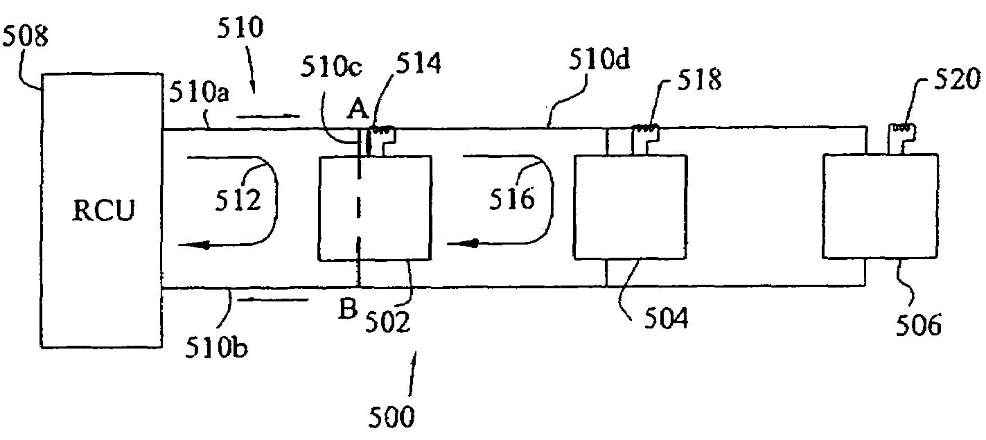
[0026]In the present invention, an amplitude domain multiplexing technique is used. This method is based on assigning a current modulation amplitude to each transmitting sensor such that the communication amplitude from any one or several transmitting sensors is unique to that one or several transmitting sensors. For example, transmitting sensors 410, 412, 414 may use a two state (idle / active) method of communication and may be assigned active communication amplitudes of 5 mA, 10 mA, and 20 mA, respectively. Accordingly, any combination of transmitting sensor communication states is uniquely distinguishable from any other combination of communication states because all of the possible combinations of states from transmitting sensors 410, 412, 414 produce a combined amplitude unique to that particular combination of states such that RCU 402 can determine the simultaneous states of all transmitting sensors 410, 412, 414. It is contemplated that other embodiments of the present inventi...


PUM


Abstract

The present invention provides a system of and a method for multiple transmitters to communicate data over a single uni-directional communication bus. In one form of the present invention, a data communication system using time-domain multiplexing includes a uni-directional current-modulated communication bus, a plurality of sensors coupled to the communication bus, at least one of the sensors capable of detecting the data transmission of a sensor outside of the current loop of the first sensor, the sensors also capable of transmitting data on the communication bus using current loop modulation. In another form of the present invention, a method of transmitting data on a uni-directional communication bus is provided. The method includes the steps of enabling a first device to transmit a data signal on the communication bus, the data transmission followed by an idle period, and the first device including a current sensor; enabling a second device to detect the first device's data transmission and the idle period; and enabling the first device to transmit data upon detecting the idle period, the first device positioned in a first current loop and the second device positioned in a second current loop outside of the first current loop, the second current loop passing through the current sensor of the first device.

Description

[0001]This application claims the benefit of U.S. Provisional Patent Application No. 60 / 491,098 filed on Jul. 30, 2003.TECHNICAL BACKGROUND[0002]The invention generally relates to communication systems. More specifically, the field of invention is crash sensing systems.BACKGROUND OF THE INVENTION[0003]Crash sensing systems are used in vehicles to control restraints (e.g. air bags, pretensioners, etc.) in order to prevent or reduce injury to occupants of vehicles resulting from collisions with other vehicles or objects. The performance of these crash sensing systems is highly dependent on data from transmitting sensors in various locations on the vehicle, especially those transmitting sensors near a point of contact in the collision event. The proximity of these sensors to the point of contact places them within the “crush zone,” which is the portion of the vehicle structure that is deformed, or crushed, by the collision event.[0004]Transmitting sensors in the “crush zone” of the veh...

Claims


Application Information

Patent Timeline
Patent Type & Authority Patents(United States)
IPC IPC(8): H01R39/00G06F13/00B60R21/01
CPCB60R21/013H04B3/50B60R2021/01068B60R2021/01115B60R2021/01109
Inventor CLUFF, CHARLES A.
Owner APTIV TECH LTD
Why Eureka
Try Eureka