Storage unit, condition monitoring program product, and condition monitoring program storage medium

a technology of condition monitoring program and storage unit, applied in the direction of digital recording/recording, instruments, input/output to record carriers, etc., can solve the problems of fatal failure, optical disk unit unrecognizable, optical disk unit defective, etc., and achieve accurate and easy operation

Inactive Publication Date: 2007-03-13
FUJITSU LTD
View PDF16 Cites 16 Cited by
  • Summary
  • Abstract
  • Description
  • Claims
  • Application Information

AI Technical Summary

Benefits of technology

[0021]The second storage unit of the present invention allows trouble shooting to be performed accurately and easily because a history of abnormal conditions occurring in the unit is associated with and stored with date information and the associated date information significantly affects the trouble shooting.
[0022]The third condition monitoring program storage medium of the present invention contains the condition monitoring program which analyzes an abnormal condition history with which date information is associated and presents a message to the user according to the abnormal condition history, thereby allowing the user to take measures such as head cleaning or purchasing a new product before the abnormal condition results in any serious failure.

Problems solved by technology

As is often the case, an abnormal condition in such a storage unit, an optical disk unit, for example, cannot be found until it results in a data failure in the process of practically using the optical disk unit, the optical disk unit becomes unrecognizable to the host computer to which it is connected, or other abnormal symptoms such as unusual noise or abnormal lighting of an LED indicator that are obvious to a user occur.
However, when the user notices the abnormal condition, it may have resulted in a fatal failure.
If such a failure occurs and the user sends the unit for repair or buys a new one, he or she does so without identifying which part of the unit has failed or what kind of failure has occurred.
For example, if the optical disk unit has no failure but instead an optical disk loaded in the optical disk unit is defective, the user may misconceive that the optical disk unit is defective and sends the disk unit for repair or buys a new one.
Or, if the nature of a failure is such that repairing the unit is more expensive than buying a new one but the user does not know it, he or she may send it for repair.
Conversely, even if the failure can be easily remedied, the user may buy a new, expensive unit.
The technology proposed in that application only increases the number of aspects of abnormal conditions, such as data failure, abnormal noise, and abnormal lighting of LED indicators, that are obvious to a user by one.
It also cannot report abnormal signs to the user in an earlier stage or incorporate in the criterion user's concept as to whether he or she treats it as a failure.
As a result, head cleaning is not performed, resulting in abnormal conditions.
However, a user receiving the report cannot know what to do about the problem and may uninformedly send the unit for repair.
However, this information alone cannot show the exact elapsed time.
This is because the computer to which the storage unit is connected can be updated or data storage means (a hard disk drive, for example) within the computer can be updated when it fails and, as a result, it can become impossible to exactly know the date on which the storage unit was first brought into use.
However, users do not always register themselves with the system.
The system therefore is insufficient in terms of keeping track of the elapsed time.
None of the above-described applications describe an approach to keeping track of time elapsing since a storage unit was brought into use.

Method used


Image

  • Storage unit, condition monitoring program product, and condition monitoring program storage medium
  • Storage unit, condition monitoring program product, and condition monitoring program storage medium
  • Storage unit, condition monitoring program product, and condition monitoring program storage medium

Examples


Embodiment Construction

[0053]An embodiment of the present invention will be described below.

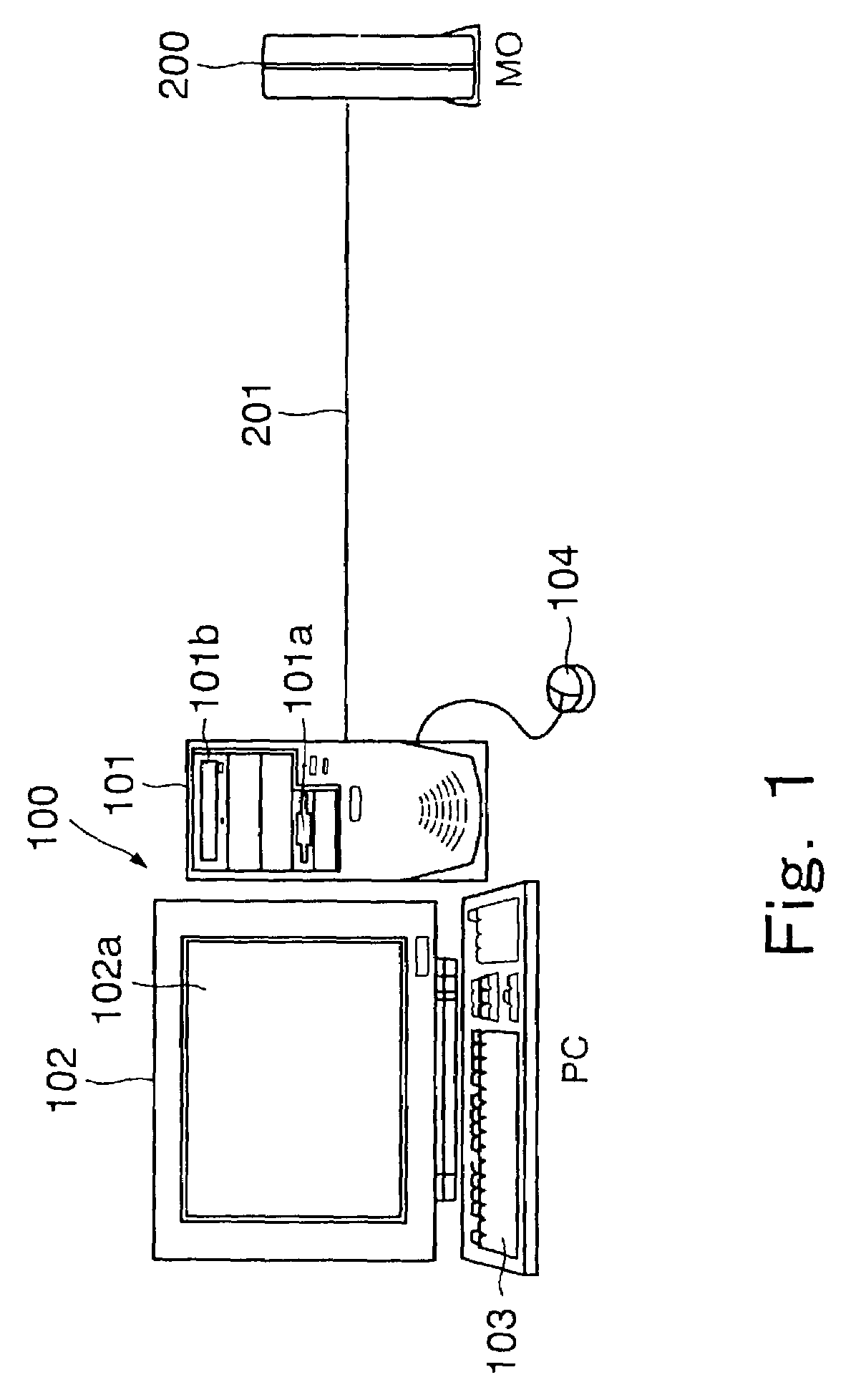
[0054]FIG. 1 is an external view of a personal computer to which an optical disk unit (MO), which is one embodiment of a storage unit according to the present invention, is connected.

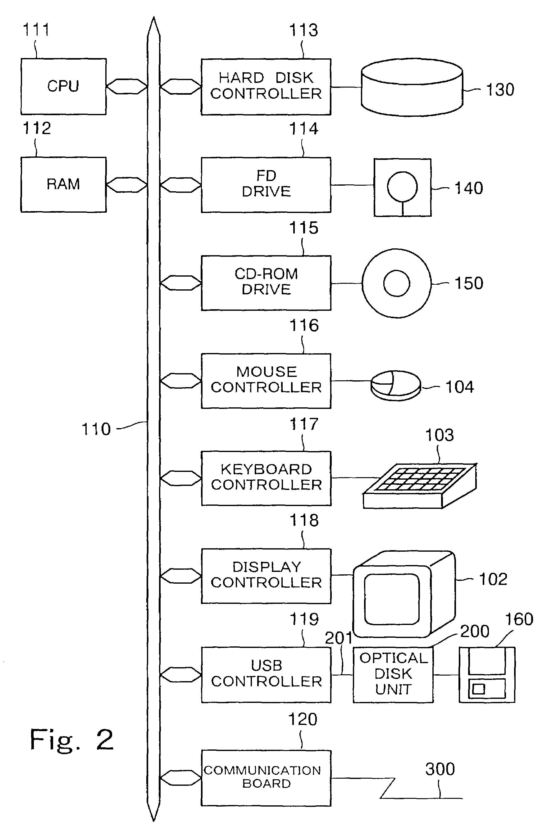
[0055]A personal computer (PC) 100 shown in FIG. 1 includes a main unit 101 containing a Central Processing Unit (CPU), a random access memory (RAM), a hard disk, a communication board, and other components, a display unit 102 for displaying images and text on a display screen 102a in accordance with an instruction from the main unit 101, a keyboard 103 for inputting instructions of a user into the personal computer 100, and a mouse 104 for pointing a position on the display screen 102a to input an instruction related to an icon displayed in the pointed position.

[0056]Viewing from outside, the main unit 101 further includes an FD slot 101a through which a flexible disk (FD) is inserted and a CD-ROM slot 101b through which a CD-ROM is i...


PUM

PropertyMeasurementUnit
timeaaaaaaaaaa
frequencyaaaaaaaaaa
timeaaaaaaaaaa

Abstract

The present invention provides a storage unit for accessing a storage medium according to a direction from a computer, a condition monitoring program product executed in the computer to which the storage unit is connected, and a storage medium thereof, having a configuration advantageously providing information for a user to properly address an abnormal condition in the storage unit. The storage unit includes a date storage module for storing a current date reported from the computer only a first time the storage unit is connected to the computer and maintains subsequently the date. The condition monitoring program receives the date stored in the date storage module from the storage unit connected to the computer and presents a message according to the number of days elapsing between the date and the current date.

Description

BACKGROUND OF THE INVENTION[0001]1. Field of the Invention[0002]The present invention relates to a storage unit connected to a host apparatus, such as a computer, for accessing a storage medium according to a direction from the host apparatus, a condition monitoring program product executed in the host apparatus to which the storage unit is connected for configuring in the host apparatus a condition monitor that monitors conditions of the storage unit, and a condition monitoring program storage medium storing the condition monitoring program.[0003]2. Description of the Related Art[0004]Storage units for accessing storage media have been widely used as computer peripherals.[0005]As is often the case, an abnormal condition in such a storage unit, an optical disk unit, for example, cannot be found until it results in a data failure in the process of practically using the optical disk unit, the optical disk unit becomes unrecognizable to the host computer to which it is connected, or ot...

Claims


Application Information

Patent Timeline
Patent Type & Authority Patents(United States)
IPC IPC(8): G06F11/00G06F11/34G06F3/06G06F11/30G06F13/00G11B20/10
CPCG06F11/008G06F11/3055G06F11/3034
Inventor ITO, MASAHIROSUTO, KENICHIYONEKI, KENJI
Owner FUJITSU LTD
Why Eureka
Try Eureka