Modular rolling mill

a technology of modular rolling mills and rolling mills, which is applied in the field of rolling mills, can solve the problems of labor intensive procedures, reduced overall efficiency, and lack of flexibility

Inactive Publication Date: 2007-03-20
PRIMETALS TECH USA
View PDF38 Cites 26 Cited by
  • Summary
  • Abstract
  • Description
  • Claims
  • Application Information

AI Technical Summary

Benefits of technology

[0013]Since only one line shaft is employed to drive all of the rolling units, it may be directly coupled to the mill motor without having to interpose a differential gear box.

Problems solved by technology

Although block type mills are capable of rolling products at high delivery speeds, e.g., 5.5 mm rod at 120 m / sec., their overall efficiency is compromised by a lack of flexibility when changing from one product size to another.
This is a labor intensive procedure, typically taking between 20–60 minutes to complete, and occurring every 8 hours.
Although mechanically sound and advantageously flexible, as compared to block type mills, such modular arrangements are relatively complex and expensive, both to purchase and subsequently to maintain.

Method used


Image

  • Modular rolling mill
  • Modular rolling mill
  • Modular rolling mill

Examples


Embodiment Construction

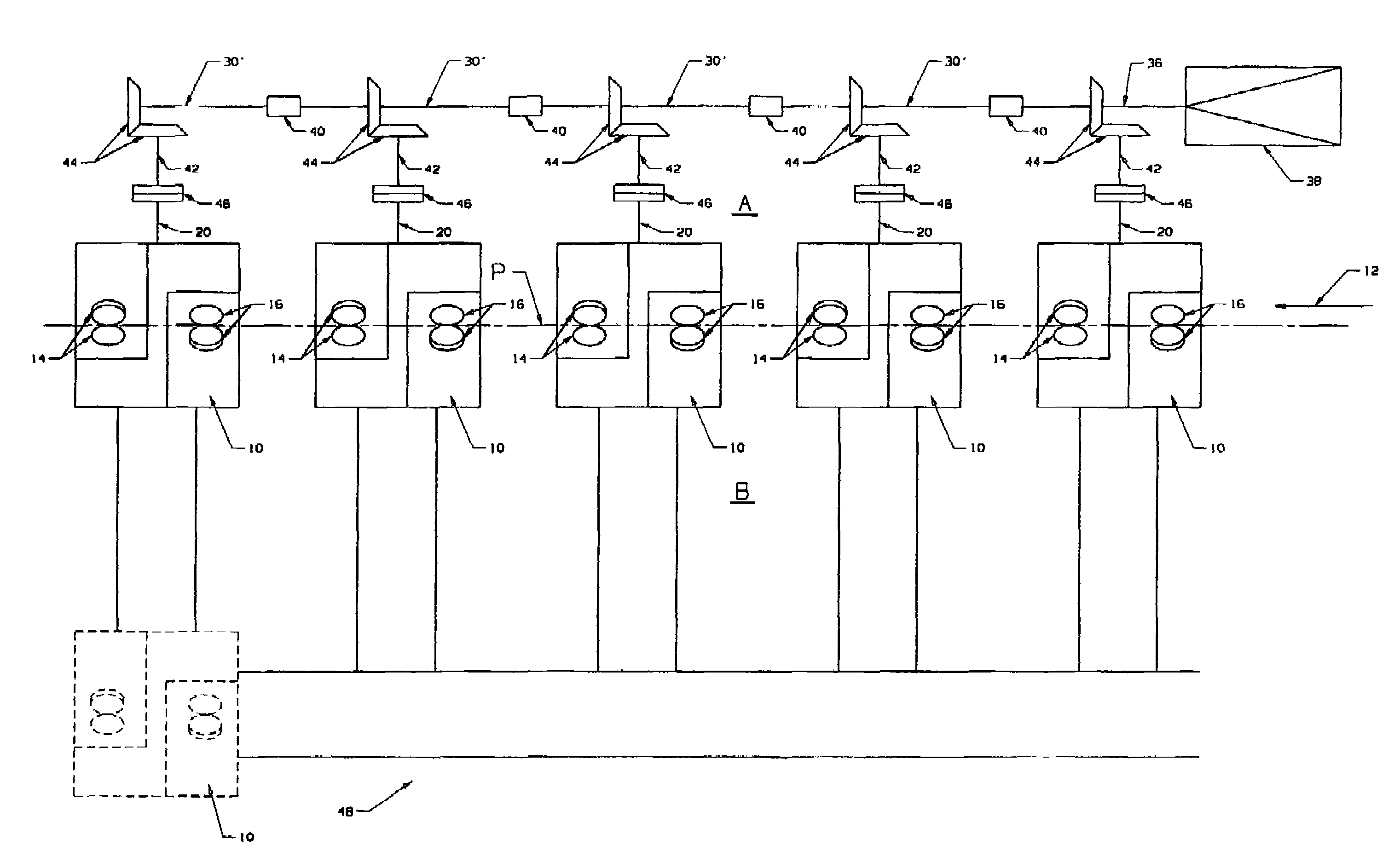
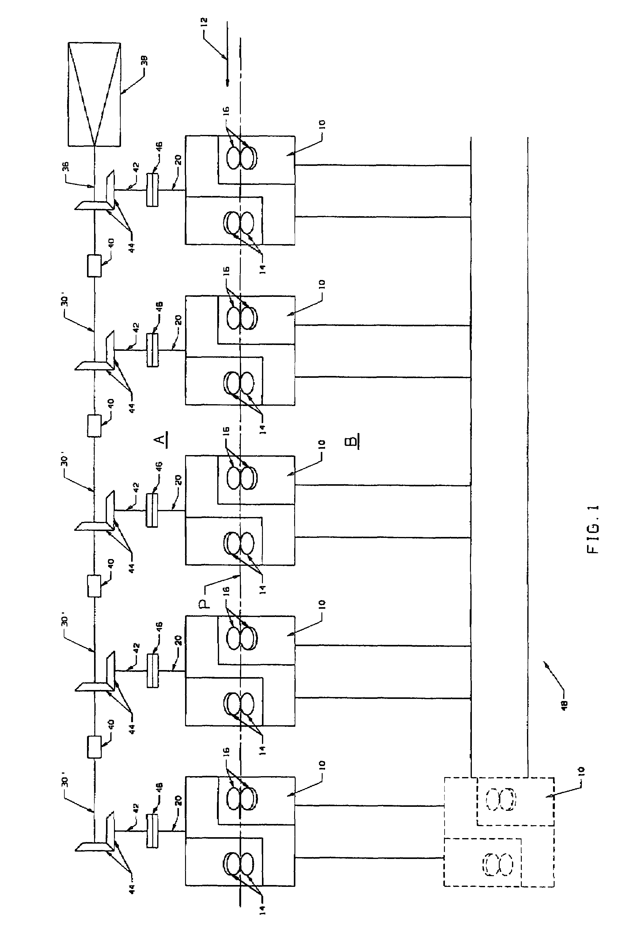
[0019]With reference to FIG. 1, a modular rolling mill in accordance with the present invention comprises a plurality of separate rolling units 10 arranged along a mill pass line “P.” The direction of rolling is indicated by arrow 12. Each rolling unit has at least two pairs of work rolls 14, 14 and 16, 16 configured to define oval and round roll passes. The rolls of each successive pair are staggered by 90° to effect twist-free rolling of long products, e.g., bars, rods, and the like.

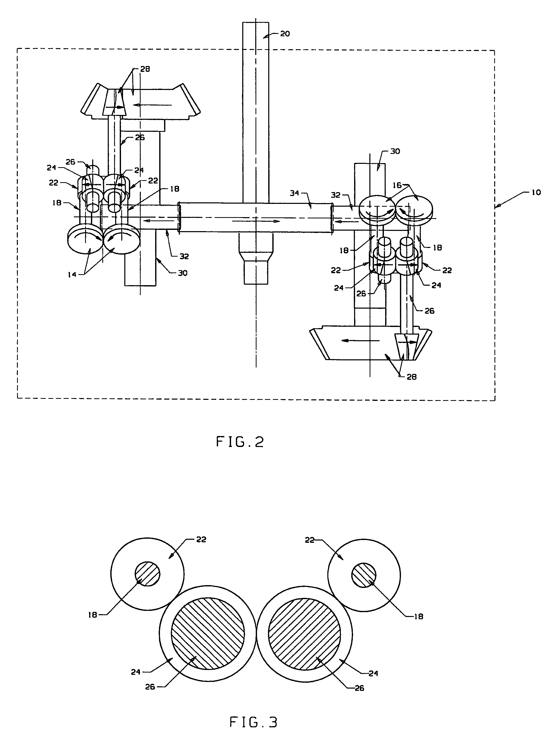
[0020]With reference additionally to FIGS. 2 and 3, it will be seen that the work rolls are mounted on roll shafts 18, and that intermediate drive trains are contained within the rolling units to mechanically couple the roll shafts to input shafts 20. The input shafts are parallel and project to a first side “A” of the pass line. The intermediate drive trains include gears 22 on the roll shafts meshing with intermeshed gears 24 on shafts 26, with one of the shafts 26 connected by a bevel gear set 28 to...


PUM

PropertyMeasurementUnit
diameteraaaaaaaaaa
feed sizeaaaaaaaaaa
diameteraaaaaaaaaa

Abstract

A modular rolling mill comprises a plurality of separate rolling units arranged along a mill pass line. Each rolling unit includes at least two pairs of work rolls defining oval and round roll passes and carried on roll shafts that are staggered 90° with respect to each other. The rolling units contain intermediate drive trains configured to connect the roll shafts to parallel input shafts projecting to a first side of the pass line from the respective rolling units. A single driven line shaft is parallel to and on the first side of the pass line. Output shafts are mechanically coupled to the line shaft by bevel gear sets. The output shafts project laterally from the line shaft towards the pass line and are connected by separable couplings to the input shafts of the rolling units.

Description

BACKGROUND DISCUSSION[0001]1. Field of the Invention[0002]This invention relates generally to rolling mills producing long products such as rods and bars, and is concerned in particular with the provision of an improved modular rolling mill.[0003]2. Description of the Prior Art[0004]Block-type rolling mills are known, as disclosed for example in U.S. Pat. Nos. 4,537,055; 5,152,165; 6,134,930 and 6,546,776. These serve primarily as finishing trains in rod rolling mills, and are in widespread use throughout the world. Block type mills comprise a series of roll stands arranged in sequence to roll an alternating oval / round pass sequence, with the roll shafts of the round roll stands being staggered by 90° with respect to the roll shafts of the oval roll stands in order to roll products in a twist free manner.[0005]Typically, the roll stands having round and oval roll passes are staggered on opposite sides of the mill pass line and are mechanically coupled to respective parallel line sha...

Claims


Application Information

Patent Timeline
Patent Type & Authority Patents(United States)
IPC IPC(8): B21B13/12B21B31/07
CPCB21B35/02B21B31/08B21B1/18B21B13/001B21B13/005B21B2013/003B21B31/10B21B39/16B21B2027/083
Inventor SHORE, T. MICHAELBOWLER, MARTYN A.
Owner PRIMETALS TECH USA
Why Eureka
Try Eureka