Adjustable angle drive for a rotary power tool

a technology of rotary power tools and angle drives, which is applied in the direction of bearings, rigid supports of bearing units, manufacturing tools, etc., can solve the problems of hard for the drill to reach the desired location, the drive is fixed at 90 degrees, and the device has not met commercial acceptance and is not commercially availabl

Active Publication Date: 2007-03-20
NOMIS
View PDF31 Cites 54 Cited by
  • Summary
  • Abstract
  • Description
  • Claims
  • Application Information

AI Technical Summary

Benefits of technology

[0006]According to another aspect of the present invention, the invention is directed toward an adjustable angle drive having a clamp that can be selectively secured and released to selectively fix or adjust the relative angular positions between input and output shafts. According to this aspect, an adjustable angle drive comprises an input shaft journalled to an input housing for rotation about an input axis and an output shaft journalled to the output housing for rotation about an output axis. A clamp releasably secures the input and output housings together and thereby fixing the input and output shafts at an angular position relative to each other. The input and output shafts are adjustable among a plurality of positions between two angular positions when the clamp is released thereby allowing movement between the input and output housings. Gearing rotatably couples the input and output shafts together such that the input and output shafts rotate in unison.

Problems solved by technology

Right angle drives are useful in a number of situations where it is difficult to orient or manipulate the drill into alignment with the working surface or where impediments make it hard for the drill to reach the desired location.
The problem with right angle drives is that the angle of such drives are fixed at 90 degrees.
Although right angle drives increase the ergonomics of drills by providing an additional angular drilling option, the problem with right angle drives is that they are still limited in that a workman only has two fixed angles to select between which insufficient and undesirable for many hard to reach spots or impediments.
To Applicant's knowledge, this device has not met with commercial acceptance and is not commercially available.
There appears to be several drawbacks and impracticalities related to this disclosed device.
Most notably, this device appears to require fastening of the device to the drill body.
Thus, the device would not appear to be readily usable with many commercially available drills and in fact would be limited to only drills having suitable mounting capabilities.

Method used


Image

  • Adjustable angle drive for a rotary power tool
  • Adjustable angle drive for a rotary power tool
  • Adjustable angle drive for a rotary power tool

Examples


Embodiment Construction

[0011]The following detailed description of embodiments of the present invention further illustrate the invention but, of course, should not be construed as in any way limiting its scope.

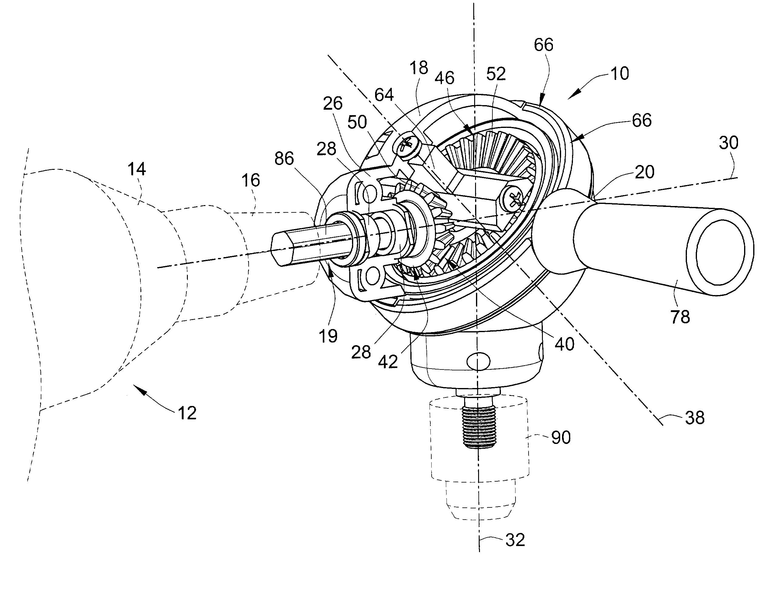
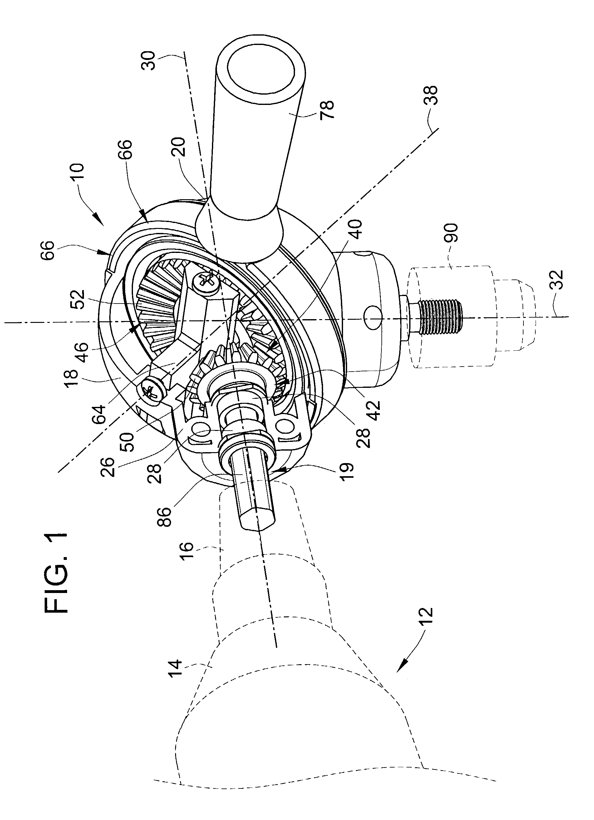
[0012]Referring to the figures, an adjustable angle drive 10 for a rotary drill 12 or other rotary power tool is illustrated. The rotary drill 12 comprises a drill body 14 and generates a rotary output through a conventional chuck 16. The angle drive 10 is shown as an attachable and detachable component for the rotary drill 12 that readily attaches and detaches to the output chuck 16.

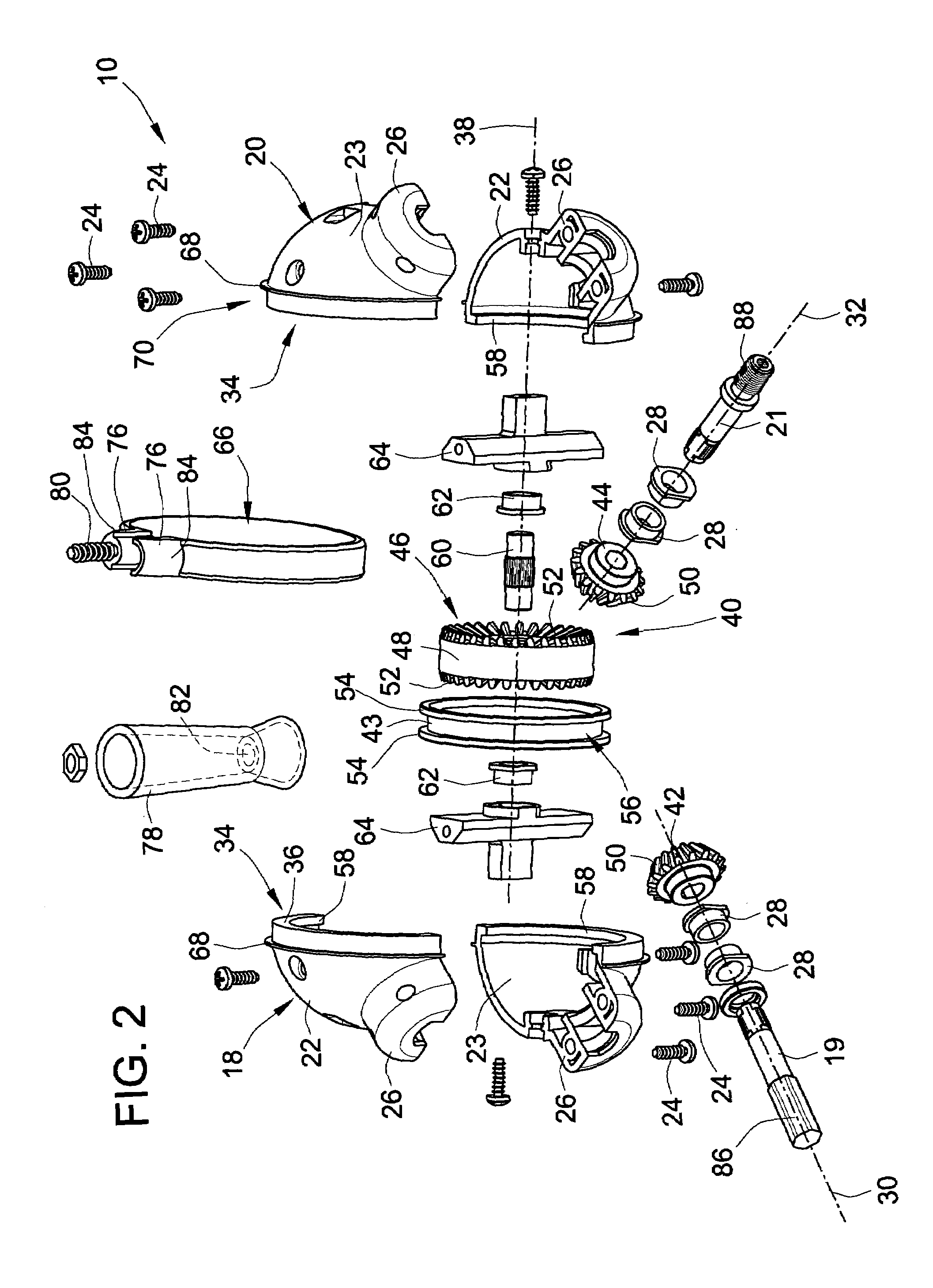
[0013]The angle drive 10 comprises an input housing 18 and an output housing 20 which carry a steel input shaft 19 and a steel output shaft 21, respectively. The input housing and output housings 18, 20 are comprised of a pair of hard plastic shells 22, 23 that can be fastened together via a screw 24 to form when combined hemispherical shells that can be used for either the output housing or the input housing. The housi...


PUM


Abstract

The present invention provides an adjustable angle drive for a rotary power tool such as a drill. The adjustable angle drive includes input and output shafts journalled for rotation in input and output housings. The input and output shafts are rotatably coupled through gearing and are adjustable among different angular positions.

Description

FIELD OF THE INVENTION[0001]This invention pertains to angular power transmitting devices and more particularly to adjustable angle drive transmissions for rotary power tools such as a rotary power drill for example.BACKGROUND OF THE INVENTION[0002]Right angle drives, such as generally exemplified in U.S. Pat. No. 2,620,840, are commonly used in rotary power drill applications to convert the axis of rotation by 90 degrees. Right angle drives are useful in a number of situations where it is difficult to orient or manipulate the drill into alignment with the working surface or where impediments make it hard for the drill to reach the desired location. Such right angle drives are relatively simple in construction and can be readily used with all or most commercially available rotary drills. Right angle drives can be readily attached and detached from the chucks of rotary drills to allow for quick adaptation of the drill. The problem with right angle drives is that the angle of such dri...

Claims


Application Information

Patent Timeline
Patent Type & Authority Patents(United States)
IPC IPC(8): F16C35/06B25B17/00B23Q5/04F16H1/14
CPCB23Q5/045F16H1/14Y10T74/19665Y10T74/19688Y10T74/19565
Inventor BARKDOLL, PATRICK J.
Owner NOMIS
Why Eureka
Try Eureka