Method and system for mission module swapping in a vessel

a technology for mission modules and ships, applied in special purpose vessels, vessel construction, passenger handling apparatus, etc., can solve the problems of incompatibility with another type of mission, inefficient hulls of multi-mission ships, and inability to meet the needs of multi-mission ships, so as to achieve quick and easy swapping and provide the ship with different mission capabilities.

Active Publication Date: 2007-03-20
LOCKHEED MARTIN CORP
View PDF29 Cites 1 Cited by
  • Summary
  • Abstract
  • Description
  • Claims
  • Application Information

AI Technical Summary

Benefits of technology

[0008]By interchanging mission modules, a crew can quickly and easily provide the ship with different mission capabilities. More specifically, by designing a hull structure with a bay for different types of mission modules, a first module designed to provide systems and facilities for a first type of mission can be removed and a second mission module designed to provide systems and facilities for a second type of mission can be installed. Because the interfaces between each mission module and the hull structure and / or the ship's control systems are typically compatible for most mission modules, retrofitting a ship for a different mission is achieved quickly and easily.
[0009]Furthermore, because the mission modules are easily interchanged, a ship may be retrofitted while deployed. That is, a ship may jettison a first mission module and then acquire a new mission module without the requirement of leaving the operating theater and transiting to friendly port or to a dry dock.

Problems solved by technology

The ship may also have a hull that, although not ideal for any particular type of mission, is at least compatible with all of the mission types for which the ship is designed.
One problem with such a multi-mission-type ship is that it is often larger than it needs to be for a single type of mission.
Another problem is that multi-mission-type ships are typically inefficient.
Furthermore, the hull of such a multi-mission ship is typically not ideal for any of the mission types for which the ship is designed.
That is, if the hull is ideal for one type of mission, it may be incompatible with another type of mission.

Method used


Image

  • Method and system for mission module swapping in a vessel
  • Method and system for mission module swapping in a vessel
  • Method and system for mission module swapping in a vessel

Examples


Embodiment Construction

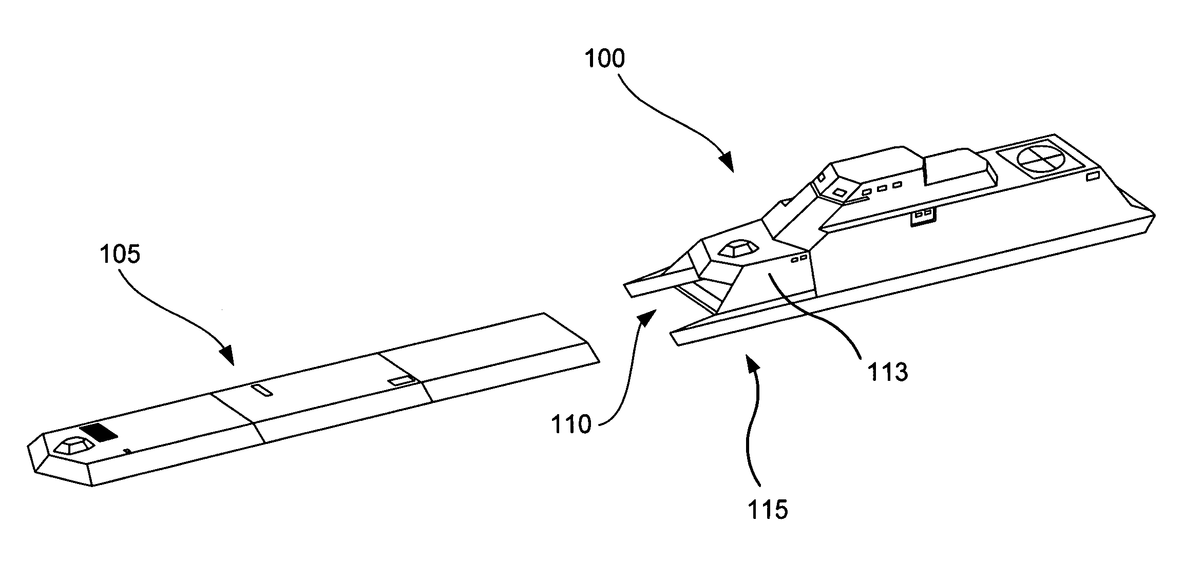
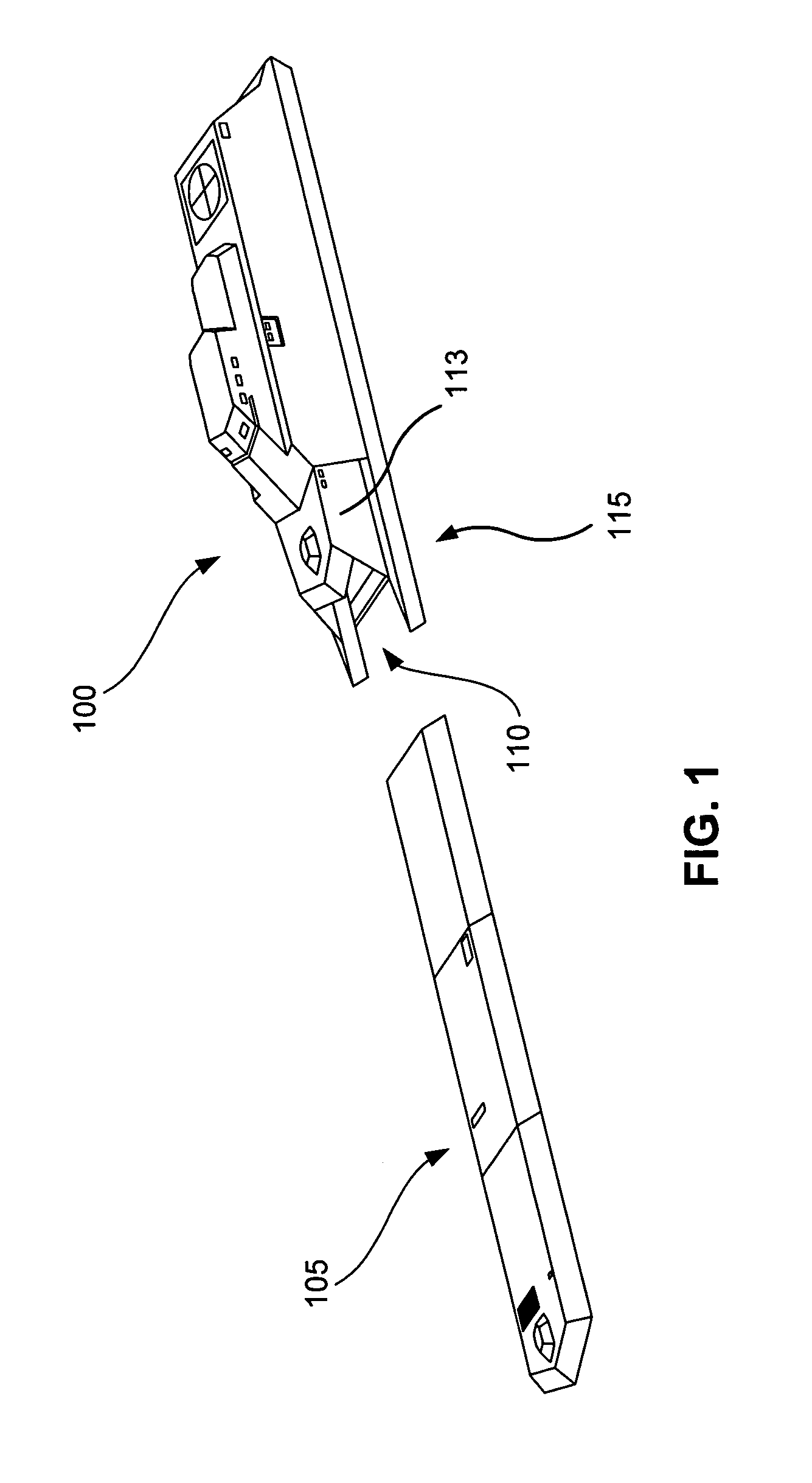
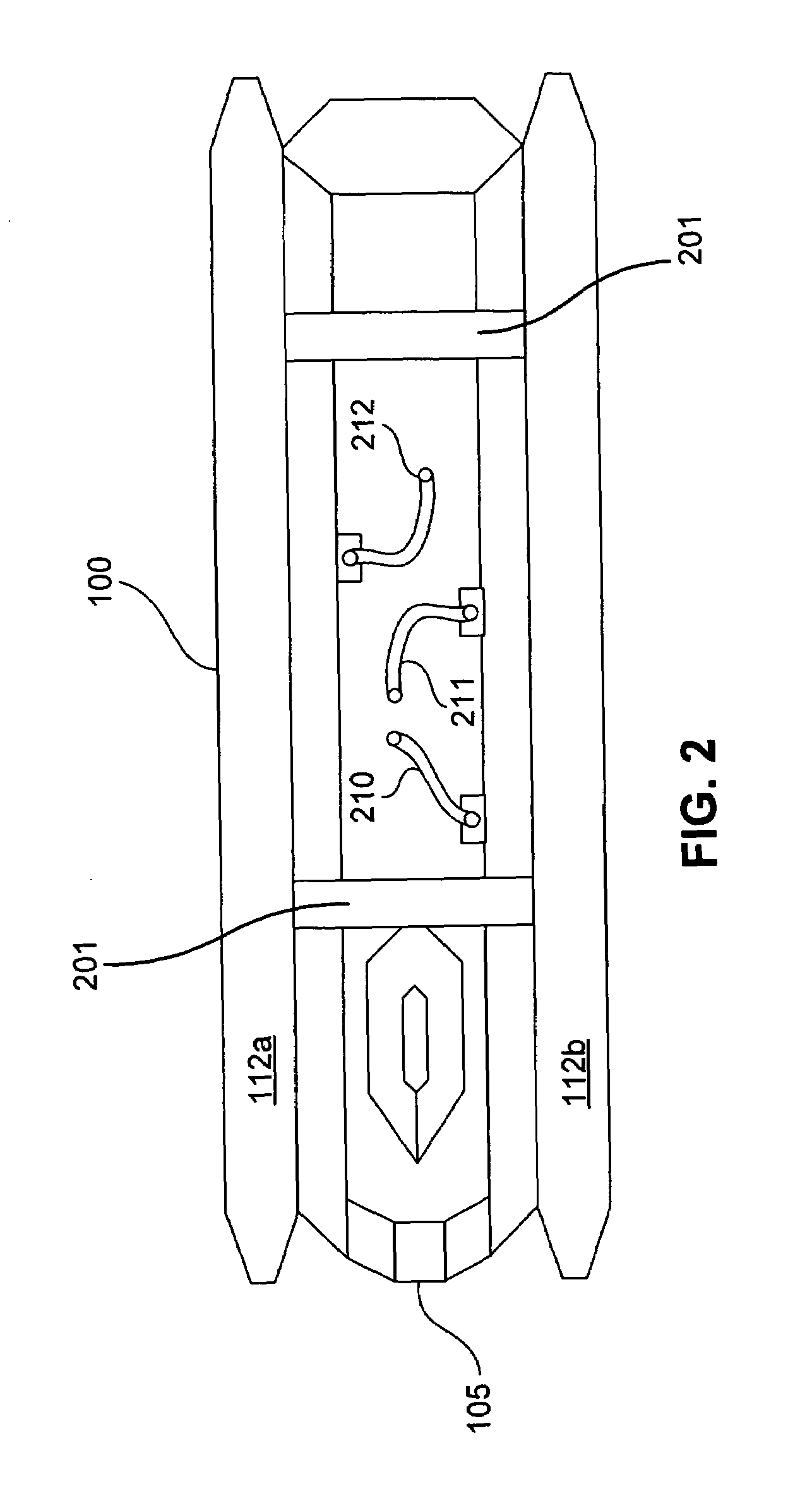
[0016]FIG. 1 is an isometric view diagram of a multi-mission ship 100 and an associated mission module 105 according to an embodiment of the invention. The ship 100 may be a monohull, a multihull (such as a catamaran, Trimaran, Pentamaran, etc.), a small-waterplane-area twin hull (SWATH), a multi-mode hull such as discussed gelow in conjunction with FIGS. 5A–5D, or other type of hullform. The ship 100 includes a hull structure or frame 115 that is designed to accept one or more mission modules 105 (only one shown in FIG. 1). The frame 115 includes two lower hull portions 112a and 112b and associated interconnecting structures (called struts hereinafter) that extend down from a main body 113, (one strut and lower hull 112a extending down from the port side and one strut and lower hull 112b extending down from the starboard side) such that a receptacle or bay 110 is enclosed by the struts and lower hulls 112a and 112b and the main body 113. The bay 110 creates a cavity such that water...


PUM


Abstract

A method for outfitting a vessel such as a water ship for a particular mission includes maneuvering the vessel toward a mission module, capturing the mission module with the vessel, and coupling the mission module to the vessel. Such method allows one to interchange mission modules, and thus outfit a vessel for different missions, quickly and easily.

Description

CLAIM OF PRIORITY[0001]This application claims priority from U.S. Provisional Application Ser. No. 60 / 426,070 filed on Nov. 12, 2002, which is incorporated by reference.CROSS REFERENCE TO RELATED APPLICATIONS[0002]This application is related to U.S. patent application Ser. Nos. 10 / 712,777 entitled MISSION MODULE SHIP DESIGN, and 10 / 712,786 entitled VESSEL WITH A MULTI-MODE HULL, which have a common filing date and owner, and which are incorporated by reference.BACKGROUND OF THE INVENTION[0003]Modern naval ships are typically designed to perform multiple types of missions, and are, therefore, referred to as “multi-mission” ships. For example, suppose a ship is designed for anti-submarine warfare, littoral warfare, and anti-mine warfare. Such a ship may include a deck that has a respective command / control station for each type of mission, i.e., a station for anti-submarine warfare, a station for littoral warfare, and a station for anti-mine warfare. The ship may also have a hull that,...

Claims


Application Information

Patent Timeline
Patent Type & Authority Patents(United States)
IPC IPC(8): B63B35/40B63B1/00B63B1/10B63B1/12B63B3/08B63B25/00B63B27/14B63B35/42
CPCB63B3/08B63B27/143B63B25/006B63B1/107B63B1/121Y02T70/14B63B35/42B64D2011/0046B64C2211/00Y02T70/10
Inventor SCHMIDT, TERRENCE W.NOLAND, GARY M.MANNINO, ANTHONY J.
Owner LOCKHEED MARTIN CORP
Why Eureka
Try Eureka