Rollercoaster launch system

a technology of rollercoaster and launch system, which is applied in the direction of helter-skelter, switchback, amusement, etc., can solve the problems of limiting accelerating the carts at the start of the ride, and unable to increase the height of the ramp without considerable costs

Inactive Publication Date: 2007-03-20
VEKOMA RIDES ENG
View PDF13 Cites 12 Cited by
  • Summary
  • Abstract
  • Description
  • Claims
  • Application Information

AI Technical Summary

Problems solved by technology

The height of this ramp cannot be increased without considerably costs.
Also constructional problems and environmental issues limit the height of this ramp.
Accelerating the carts at the start of the ride has one strong disadvantage.
The needed power of the system to pull the carts to the top of the ramp can be low because the carts do not move at high speeds.

Method used


Image

  • Rollercoaster launch system
  • Rollercoaster launch system
  • Rollercoaster launch system

Examples


Embodiment Construction

[0021]Before explaining the present embodiments in detail, it is to be understood that the embodiments are not limited to the particular embodiments herein and it can be practiced or carried out in various ways.

[0022]An object of the embodied systems is to provide a roller coaster launching system wherein the above-mentioned drawbacks are avoided at least to a considerable extent.

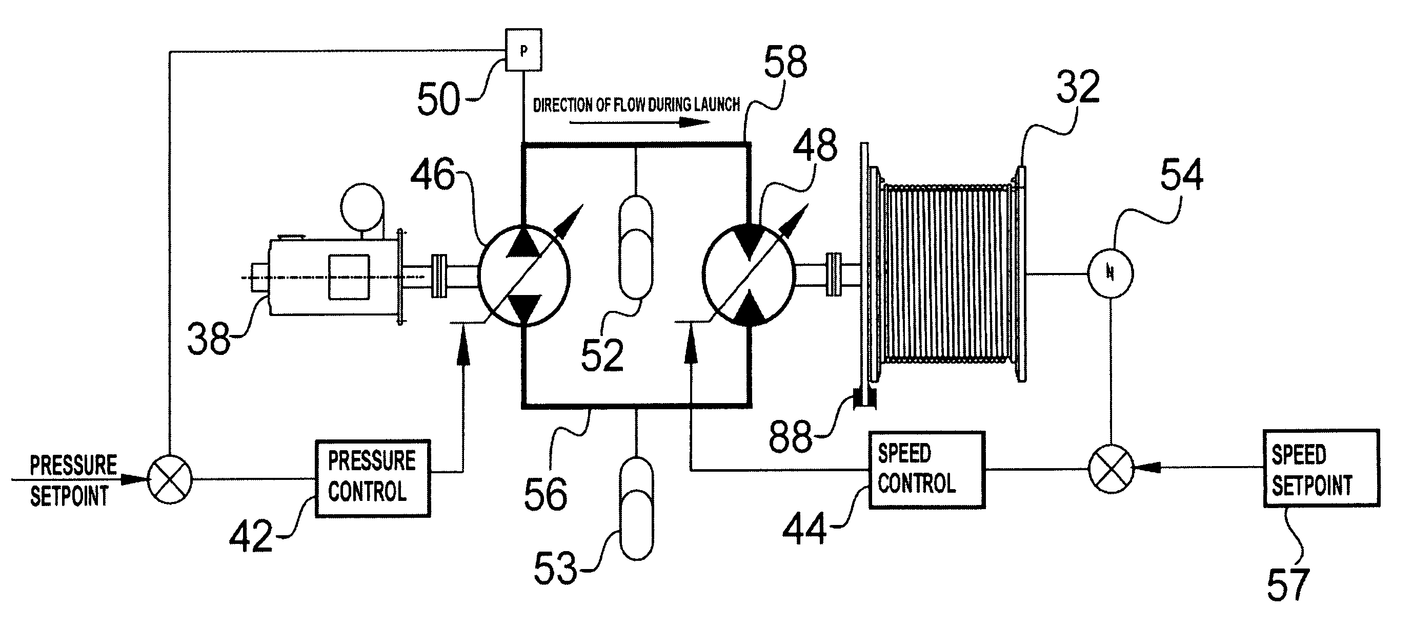
[0023]The basis of the launching system is formed by a secondary-controlled winch system. In a secondary-controlled winch system, the displacement of the hydro motor connected on one end to the winch drum is variable. The hydraulic motor is directly connected to the constant pressure circuit. The delivered torque and speed of the motor is controlled only with the variable displacement of the hydro motor. If the torque delivered by the motor is greater than the needed torque for the load, the motor hoists the load. If the torque delivered by the motor is less than the torque needed for the load, the load is ...


PUM


Abstract

A winch system, typically used in a roller coaster system, includes a hydraulic pump, a variable speed motor connected to the hydraulic pump, a first pipe connected to the hydraulic pump; a second pipe connected to the hydraulic pump comprising a second pressurized fluid; an accumulator system connected the pipes; a motor connected to the accumulator system; and a winch drum connected to the motor.

Description

[0001]The present application is a divisional of U.S. patent application Ser. No. 10 / 195,295 filed on Jul. 15, 2002 now U.S. Pat. No. 6,837,166.FIELD[0002]The present embodiments relate to a rollercoaster launching system and booster system with an increased efficiency as to lower the maximum power of the launching system.[0003]The present embodiments also relate to a method for both launching and stopping the rollercoaster carts.BACKGROUND OF THE INVENTION[0004]In general, rollercoasters are useful amusement park devices comprised of a car supported in a frame that causes the cart to follow a path where the rider experiences high speeds and gravitational forces due to loops, turns and drops. In conventional rollercoasters the carts are pulled to the top of a ramp to provide the carts with the energy needed to complete the ride. During the ride the carts convert the gained potential energy into kinetic energy i.e. speed.[0005]Since the potential energy is dependent on the height of ...

Claims


Application Information

Patent Timeline
Patent Type & Authority Patents(United States)
IPC IPC(8): B66D1/10A63G7/00
CPCA63G7/00
Inventor ROODENBURG, JOOPDE VIN, PETER
Owner VEKOMA RIDES ENG
Why Eureka
Try Eureka