Solar concentrator array with grouped adjustable elements

a solar concentrator and array technology, applied in the field of solar concentrator arrays, can solve the problems of arrays that are relatively heavy, arrays that are undesired, and require a large amount of motorized equipment, so as to reduce the number of motors required for the entire tracking heliostat array, reduce the cost, complexity and weight of the array

Inactive Publication Date: 2007-03-20
CYRIUM SOLAR
View PDF55 Cites 198 Cited by
  • Summary
  • Abstract
  • Description
  • Claims
  • Application Information

AI Technical Summary

Benefits of technology

[0005]An improved tracking heliostat array has been developed. In an exemplary embodiment, as few as one motor can be used to simultaneously adjust the orientation of all optical elements in the array. This configuration allows the number of motors required for the entire tracking heliostat array to be reduced as compared to many conventional heliostat arrays. By reducing the number of motors, one embodiment advantageously reduces the cost, complexity and weight of the array as compared to a conventional tracking heliostat array having dedicated motors associated with each optical element. Therefore, such an array is well-suited for use in decentralized small-scale applications and / or weight sensitive applications, such as individual rooftop mounted residential systems. However, such an array can also be used in large-scale, ground based applications.

Problems solved by technology

In a conventional tracking heliostat array, configuring each optical element to be individually movable typically requires a large amount of expensive motorized equipment.
In addition to causing the array to be undesirably expensive, this large amount of motorized equipment results in an array that is relatively heavy, which is particularly disadvantageous for applications where weight is a significant factor, such as for rooftop mounted applications.

Method used


Image

  • Solar concentrator array with grouped adjustable elements
  • Solar concentrator array with grouped adjustable elements
  • Solar concentrator array with grouped adjustable elements

Examples


Embodiment Construction

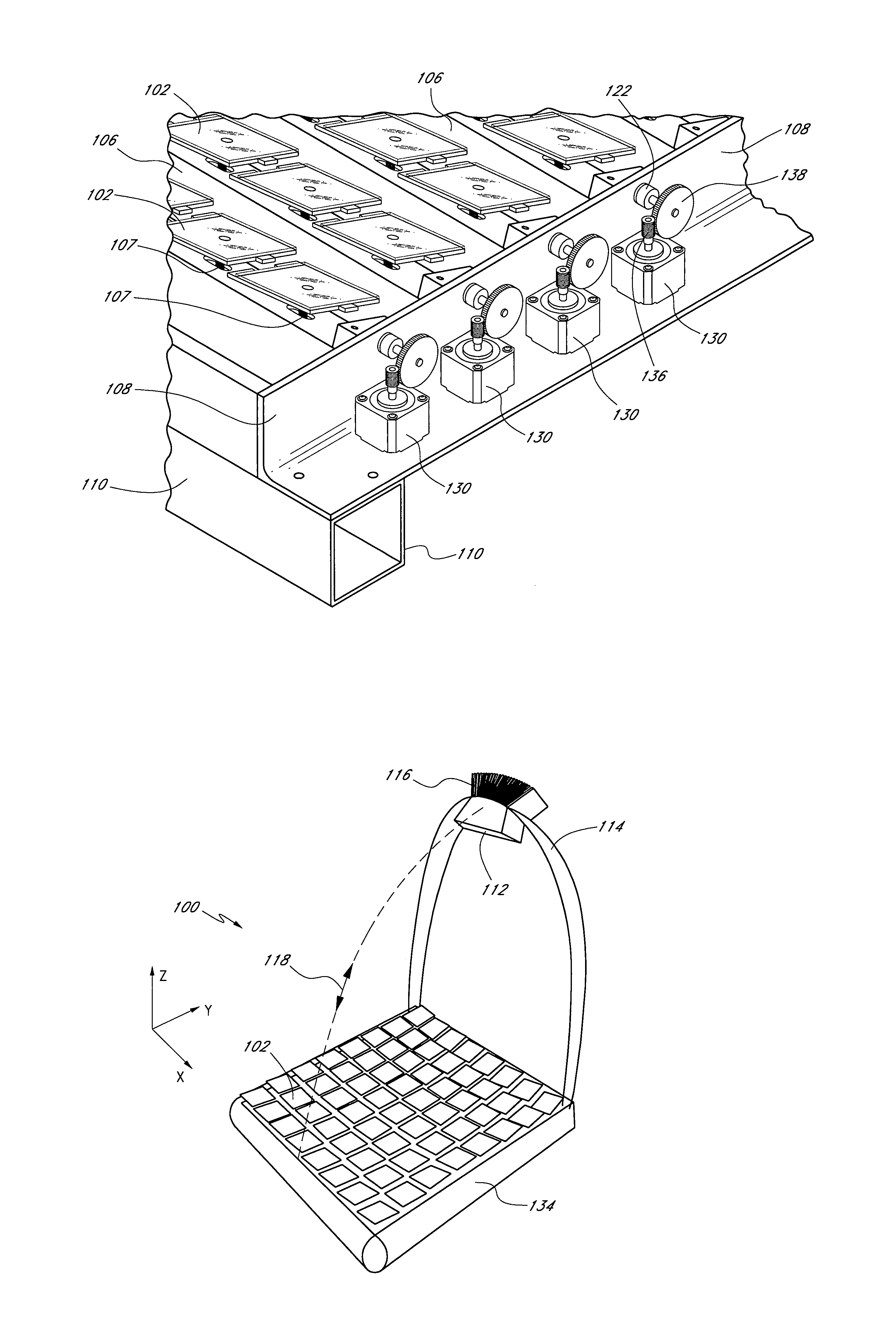
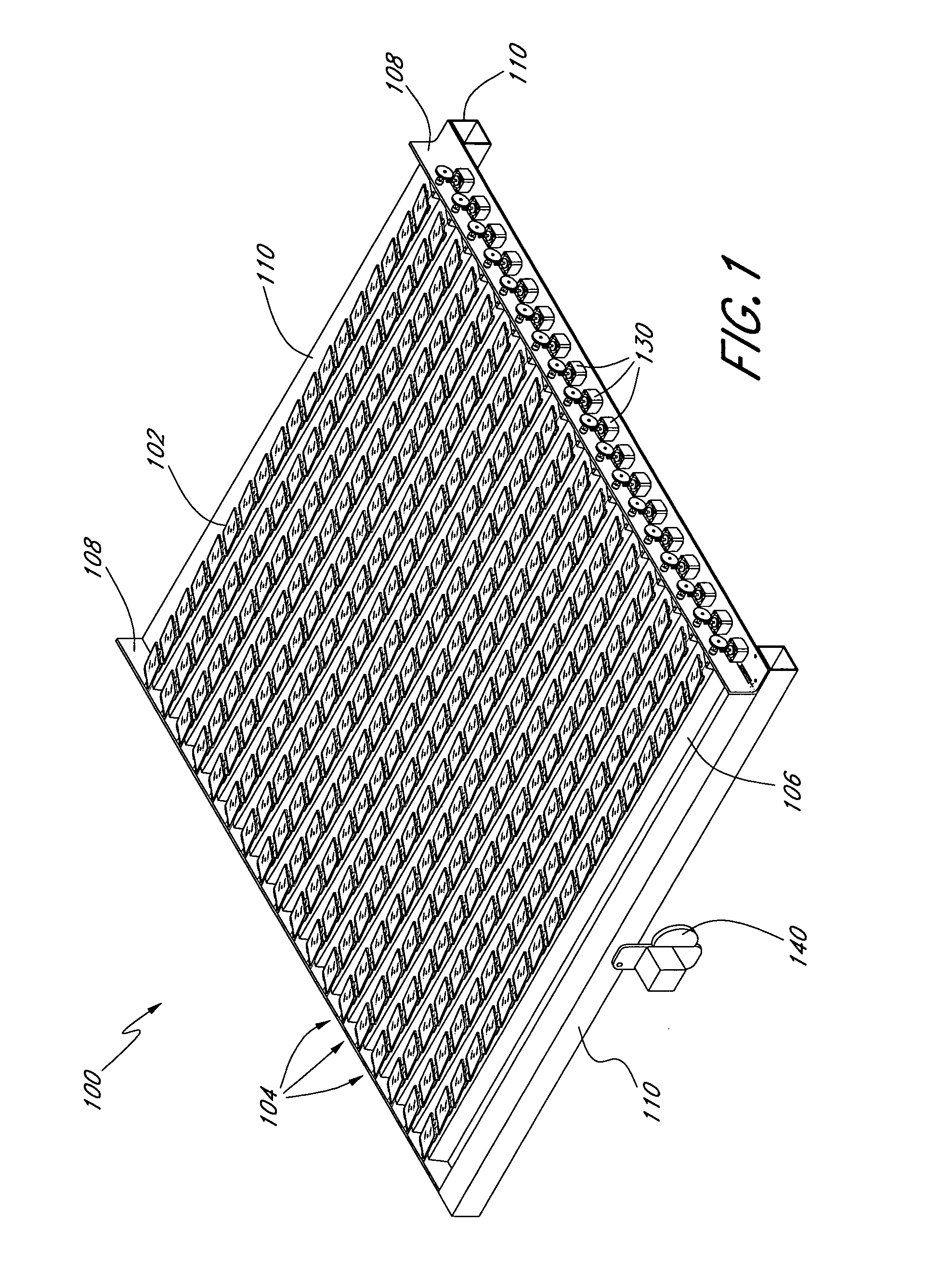
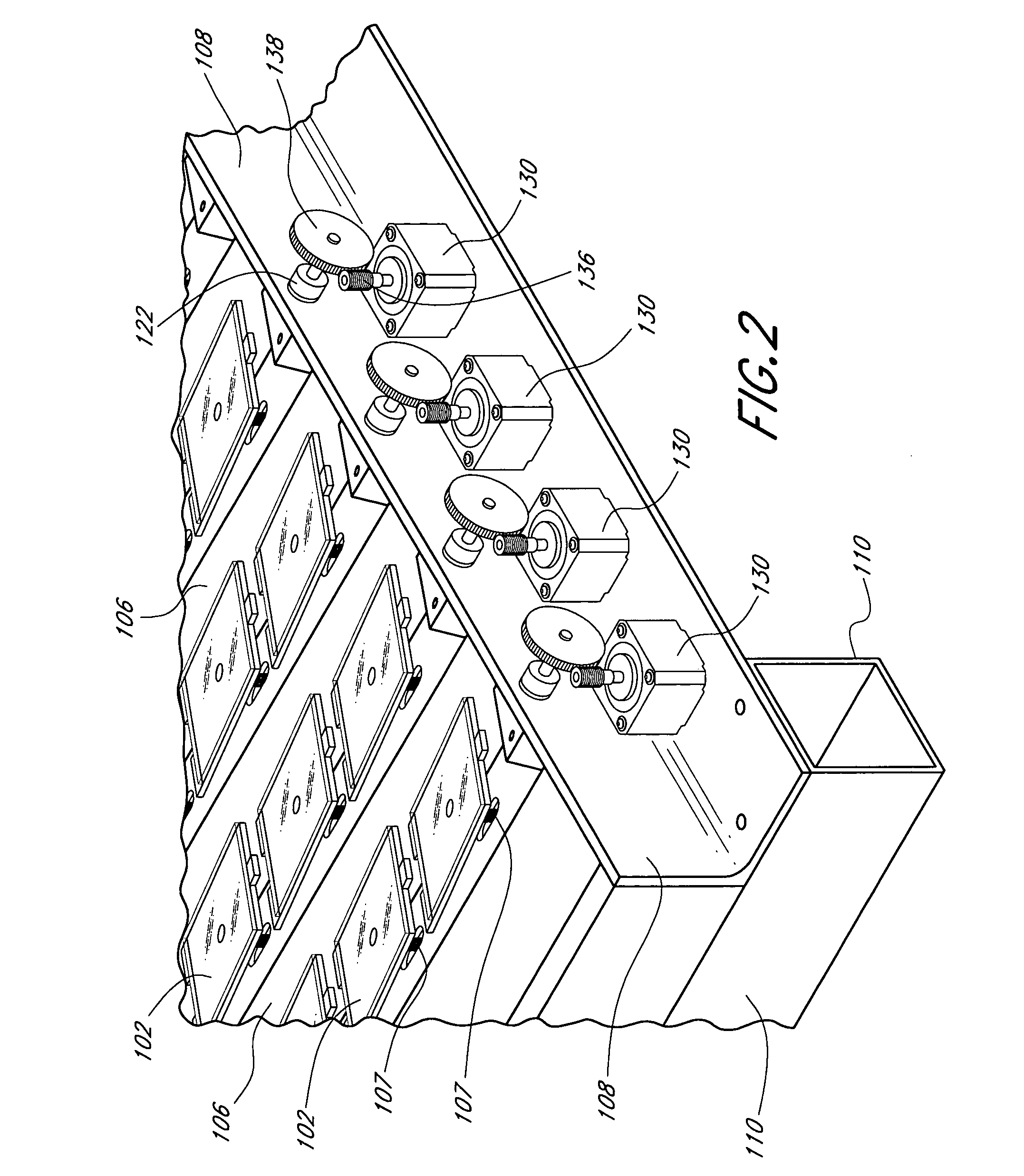
[0028]As described herein, an improved tracking heliostat or solar concentrator array having adjustable optical elements has been developed. By using one or more motors to adjust the orientation of group of optical elements, fewer overall motors are required as compared to a conventional array having dedicated motors associated with each optical element. Additionally, the motors used to adjust the orientation of optical elements often require environmental protection, and therefore conventional tracking heliostat arrays having motors associated with each optical element often are placed within a protective enclosure. This can adversely affect the solar concentrator by reducing the amount of solar energy that is reflected from the optical elements, and by increasing the weight and cost of the array.

[0029]Therefore, by using one or more motors to adjust the orientation of more than one optical element, several advantages can optionally be obtained. For example, the improved tracking h...


PUM


Abstract

A ground-based tracking heliostat array comprises a first plurality of elongate row mounts. The elongate row mounts are positioned at least partially between, and are supported by, a first side bracket and a second side bracket. The row mounts are rotatable in a first axis. The array further comprises a plurality of optical elements that are mounted to one or more of the elongate row mounts. The array further comprises a linkage that is mechanically coupled to a first plurality of elongate row mounts. Movement of the linkage causes the first plurality of elongate row mounts to simultaneously rotate in the first axis. The array further comprises a motor configured to move the linkage.

Description

PRIORITY APPLICATIONS [0001]This application claims the benefit of U.S. Provisional Patent Application 60 / 490,746 (filed 28 Jul. 2003) and U.S. Provisional Patent Application 60 / 516,025 (filed 31 Oct. 2003). The entire disclosure of both of these priority applications is hereby incorporated by reference herein.FIELD OF THE INVENTION [0002]The present invention relates generally to solar concentrators, and more specifically to an array of solar concentrators capable of tracking movement of the sun.BACKGROUND OF THE INVENTION [0003]Many solar concentrators comprise a single optical element, such as a single lens, mirror, or reflector. Examples of such concentrators include dish and trough concentrators. Other solar concentrators comprise an array of optical elements that are individually adjustable to track the position of the sun in the sky. One type of arrayed concentrator is the “heliostat array”. In a heliostat array, a field of reflective optical elements concentrates solar energ...

Claims


Application Information

Patent Timeline
Patent Type & Authority Patents(United States)
IPC IPC(8): G02B5/10H01L25/00
CPCF24J2/38F24J2/5431Y02E10/47F24S30/48F24S50/20
Inventor GROSS, WILLIAMLUCONI, GREGGZSOLNAY, DENES
Owner CYRIUM SOLAR
Why Eureka
Try Eureka